Keywords
|
| Localised, Corrosion, Pitting, Limiting factor, Marine environment. |
INTRODUCTION
|
| A pipeline system is said to be suitable for transportation of large quantities of oil and gas because there is relative freedom from impacts of weather conditions. Further more, it affords promising opportunities, for labour saving and automation and is also one of the safest and most reliable means of transportation (Shoichi, A. 1974). Petroleum and petroleum products delivery pipeline is a lifeline of the nation. Therefore, all and sundry need to be sensitized about anything that can impair the effective functionality of the system. Corrosion, which can cause damage to oil pipeline require serious attention. |
| The integrity of pipeline systems used for the transportation of crude oil and petroleum products must be sound in order to ensure risk free. Most metals occur naturally as stable oxides and since pipelines are basically made of metals and its alloys, metals that has been processed into steel tends to return to that stable state via oxidation when it reacts with its environment in the presence of moisture no matter how small. This process is termed corrosion. Hence, corrosion can be defined as “the deterioration of a substance (usually a metal) or its properties because of reaction with its environment” (NACE, 1979). |
| In petroleum operations, corrosion is inevitable, failures and consequent problems due to corrosion increases with time. Oil pipeline leakages have caused monumental damage and losses to the environment and the industries involved. Failures as result of corrosion have led to heavy loss of human lives and property, |
| When the unfortunate occurs and pipe fails prematurely in service, it is important that a satisfactory method be available for the engineering evaluation of that loss. Studies of failure not only may solve the specific problem at hand but it can provide valuable information in meeting future design needs. Premature wear or corrosion of only a few micrometers may gradually degrade performance or can render the pipe wholly unserviceable. |
| Failure has been defined to imply that a -part in service (1) has become completely inoperable, (2) is still operable but is incapable of satisfactorily perform its intended function or (3) has deteriorated seriously, to the point that it has become unreliable or unsafe for continued use (ASM Metal Handbook, 1987). |
| Failure of materials in service is usually traceable to miscalculation resulting from choice of wrong material! Improper design improper treatment or fabrication of the material, inadequately controlled environment, maintenance oversight, wrong application of anodic or cathodic protection and wrong use or application of protective coatings (NACE) 1975, Corrosion failure with a view to offering measures to reduce or prevent reoccurrence. Failure analysis is a technique by which facts are gathered and studied to determine the cause of a facility or part failure so that preventive action may be taken. It is an indispensable problem -solving tools. |
| In petroleum industries, corrosion is one of the major problems. It can be considered as an important site for pipeline failure. This takes either the form of leaks or as initiation sites for running fracture (NACE, 1998). It can take only one leak to render a length of pipeline inoperative. Therefore, it becomes apparent that keeping them in service through the prevention of corrosion is technologically and economically advantageous (Roux Teresale, 1991). |
| Pipeline may be influenced by both internal and external corrosion. Internal corrosion of pipeline depends on the composition, temperature, pressure, and flow regime of the produced fluid. Corrosion problems in oil pipelines are often minor until water cuts approach 30%. Flow lines with stratified flow that allow free water to flow or stagnate in the bottom of the flow lines may suffer corrosion problems. The corrosivity of water is significantly influenced by concentrations of dissolved gases such as oxygen, carbon dioxide and hydrogen sulphide, suspended matter and bacteria. |
EXPERMENTAL
|
| Water analysis was carried out on the produced water from the failed pipeline, the creek water (Niger Delta Creek is the failure site) that houses the pipeline and seawater for comparison using titrimetric and spectrophotometer methods. Analysis from the failed site shows that the water has the tendency of scale formation and it also contains a high concentration of chloride which when absorbed initiate pitting corrosion. Also the presence of sulphate reducing bacteria was detected when the water was cultured. The metallographic examination and analysis shows that the lower interior surface of the pipe was attacked by pitting corrosion causing perforation and eventual leakage (spillage). Several tests were carried out to determine the existence of calcium ion, magnesium ion, chloride ion, iron and sulphate ions. Similarly, total hardness of the water as well as total dissolved solids was determined. |
| Culturing, identifying and counting of the bacteria were carried out. Different types of bacteria require different culture media and some bacteria refuse to grow in artificial media, for example, iron reducing bacteria. Further more, by running the sample at several different dilutions the number of each type of bacteria can be estimated. |
| Two types of culture media were utilized; the first series utilizes 7 bottles, which contain a growth medium for general bacteria. The second series utilizes 4 bottles, which contain a different growth medium which is specific to sulphate reducing bacteria. The serial dilution method (see table 1), after inoculating the bottles were set in an incubator and allowed to incubate for a minimum of 7 days at a constant temperature of between 28°C - 30°C. |
| Non-destructive test was used to locate pits and to provide some information on their size, but they generally cannot detect small pits or differentiate between pits caused by corrosion and other types of surface defects. |
| Both ultrasonic inspection and intelligent pigging were used in order to ensure reliable information about the wall thickness of the pipelines. |
| Determination of the chemical composition of the failed pipe is necessary in order to ascertain the grade of the material and hence the expected mechanical properties. Therefore, chemical analysis of the failed pipe sample was determined by means of solid-technique, optical emission spectrography. It Involves pin-to-pin spark method with direct, computerized reading spectrometer for a variety of elements. The results show that, generally the pipe is made of high grade of low-alloy steels with some amount of silicon. |
| Specimens were cut from the failed pipe pieces for metallographic studies using an. abrasive cutting wheel. Coolant (Metaserv) was used on the material to avoid over heating while the cutting was going on. Rough grinding was performed using hand grinder (silicon carbide abrasive papers). This was followed by fine grinding using another hand grinder (Aluminium oxide paper). Water is the coolant used in both cases and the grindings were carried out to remove the cutting lines from the specimens. |
| Polishing of the specimens with the universal polisher with diamond pastes (6 micron & 1 micron) was successively performed. A flat and scratch free sur - face finish was ensured by microscopically examining the specimens. The etching process involve immersion of the prepared specimens in 2.0% Nital (Nitric alcohol) which is the etching solution for minute per specimen (Nitric alcohol is made up of 98% absolute ethanol & 2% concentrated nitric acid). The specimens were then washed with water and allowed to dry in the specimen dryer. |
Results
|
| During visual inspection of the external surface of the failed pipe, metabolic action of marine plants and animals on the coating was observed. After scraping, it was found that the coatings were weak and perforated, which allowed penetration of water to the surface of the pipeline. This resulted to severe and localised pitting corrosion. Similarly, visual inspection of the internal surface shows that most of the internal surface was covered by scales and bacterial metabolites was noticed under the scales. Also, under these porous scales were corrosion pits located at the bottom quadrant (6 o’clock position). |
| The analysis of the corrosion products and residual scale/debris were carried out and it was found that the scale is made up of magnetite, iron sulphide and calcium carbonate. From the water analysis result, the scale indices computation shows that there is the tendency of scale formation in the produced water and seawater with the presence of bacteria, especially sulphate reducing bacteria whose activities result in pitting corrosion. |
| Corrosion rate determined using coupons show that the seawater is more corrosive than the tap water. This may be as a result of high concentration of aggressive ions such as chloride which helps in the propagation of corrosion reaction and eventual initiation of pits on the metal surface. |
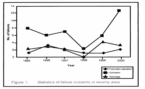
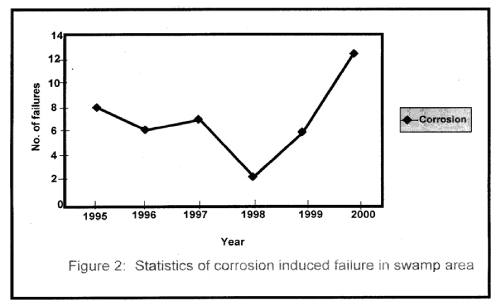
| Figure 1 shows the statistical representation of failure that took place in the swamp area for the period under investigation. Similarly, Figure 2 represents corrosion induced failure that took place in the area of one of the oil companies operating in the Niger Delta Region. |
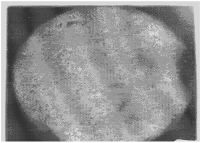
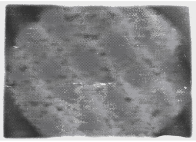
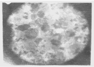
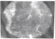
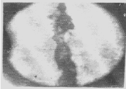
| Apart from the pitting type of corrosion, metagraphic examination and analysis show that some other forms of corrosion have occurred at the bottom guardant of the pipe leading to severe reduction in wall thickness from 12mm to 1 mm which was unable to hold a normal operating pressure of 330psi. Figures 3 to 7 shows photomicrograph of the flat internal surface of the pipeline at different positions around the failed area of the pipeline. Macroscopically, there was no visible sign of cracks or failure spots. But, it can be seen that the material suffered from pitting corrosion. |
| Figure 5 confirms that pitting corrosion was the cause of the patches and roughened surface of the pipeline. Figure 6 shows areas covered by scales, .which have allowed corrosion activities to continue under it. Whereas, Figure 7 reveals visible cracks initiated by pits overlapping each other. |
| For the ultrasonic inspection, the terrain of the pipe location was swampy, sandy and floody with continuous collapse of soil during excavation. Seam pipeline was used at the upstream of reference girth weld (RGW) while pup piece at the downstream of RGW are seamless. Poor coating adhesion of dope was noticed intermittently along the decoated sections while the coating in the downstream section of the riser showed extensive breakdown. This means that the coating system was not effective and as a result, severe external corrosion was evident in the entire decoated downstream section. These corrosion pits were in clusters with some depths ranging from 0.8 to 2.2mm. |
| The results of the inspection is shown in Tables 2 to 5. And areas of internal pitting corrosion are exposed in which possible corrosion leak is envisaged on these pipelines in the nearest future if nothing is done to it. Scanning results (Table 2A-C) reveals that wall thickness has reduced from 7mm to between 2.9 and 2.1 mm and pitting length ranging from 1.5 to 1.9mm. Leakage or rupture is expected at this range of deterioration. |
| Discussion |
| The failed flow line (pipe) which was analysed in this work is a 20inch diameter pipeline that conveyed crude at high pressure from an oil field manifold to a flow station. The failed pieces were used to examine closely -the nature of the failed part, while the non-failed piece was employed to study the chemical and mechanical properties as well as the metallographic examination. The produced water was also analysed along side the creek water that houses the pipelines. |
| The main features of the damaged pipeline are as follows: |
| (1) Most of the surface were covered by protective scales |
| (2) Corrosion pits were located on the bottom quadrant of the pipe. This may be caused by the produced water, since the water cut was 50% so, there is the tendency of water settling out of oil. |
| (3) Corrosion pits were covered by porous scale that also houses bacterial metabolites. |
| The pits were small, measuring between 5 to 15mm in diameter. Several pits overlapped each other, growing in a semi-spherical way to cause perforation. The scale indices computation shows that both sea and produced water has the tendency to .form scale which houses bacterial activities. It has been found that marine species (plants, animals, fungi, bacteria, etc) may be aggressive to materials commonly used as coatings in marine environment. These organisms may find their way to the metal surface where bare steel is exposed due to coating holidays. The activities of these organisms under the coating subsequently results in serious corrosion problems irrespective of the fact that the pipeline may be cathodically protected, as was observed during visual inspection of the external position of the failed pipeline. The reason being that the bacterial action is taking place under an electrically insulating coating film which the cathodic protection current cannot reach. |
| Figure 3 reveals the presence of small pits as well as uniform corrosion attack that may develop into wider and deeper pits leading to localized wall thickness reduction. The adsorption of negatively charged ions, such as chloride ion, creates surface dipoles which aids the passage of metal atoms through breakdown sites towards the solution (.liquid) inside the pipe resulting to pit initiation. Once the pit has been initiated, rapid dissolution of the metal within the pits occurs. Figures 4 and 5 respectively can be seen as having surfered pitting corrosion. |
| Accumulation of deposits, scale and corrosion products in the Pipeline could have promoted the pitting corrosion due to the formation of concentrated cell under the deposit/scale. Figure 6 shows tight scale deposit with corrosion activity going on beneath the scale resulting in highly localised corrosion and setting in of hydrogen embrittlement phenomenon. Figure 7 show signs of rough edges and patches of pits which may have been as a result of cracks emerging from the pits overlapping to produce a high stress concentration. Such cracks reduce the strength of the metal and it can be concluded that the failure occurred as a result of the following: |
| (i) Wall thickness reduction from 12mm to between 1mm and 2mm |
| (ii) Pits overlapping each other |
| Main corrosion mechanisms may be carbon dioxide and hydrogen sulphide with contribution from bacterial action and scale 1 debris |
| Pipelines that make up the site under investigation were equally subjected to ultrasonic inspection, intelligent pigging and visual inspection. These exercises revealed that pitting corrosion is taking place both internally and externally of the pipeline. The riser downstream which is located at the splash zone is mostly attacked by pitting corrosion both externally and internally. This probably is as a result, of differential aeration, marine life effect on the coating and pressure drop. |
| Metallic facilities submerged under water are subject to corrosion. The principal methods for mitigating corrosion of pipelines, mostly in combination are; coating, inhibitors, periodic cleaning and cathodic protection. Decisive factors of which to use and in combination with which are among other things the nature of the corrosion, the operating conditions, the constructional mechanism of the pipe and economic considerations. Small amount of inhibitor added to a process stream can reduce the corrosion reactions considerably. The corrosion inhibitors are film-forming compounds which are attracted to the metal surface to form barrier between the metal and its environment. |
| Coating as a corrosion control measure is applied as liquid, paste or powder which on solidification is firmly and continuously attached to the facility which it is designed to protect, thereby isolating it from its corrosive environment, thus preventing corrosion. Oil and gas pipelines suffer from the build up of internal deposits such as wax; scare and sand, which if left can significantly reduce the operating efficiency of the pipeline. They typically line the lower quadrant of the pipe. In severe cases the whole internal surface of the pipe may be affected. Critically, under this deposit, pitting corrosion can take place and can continue unabated, as corrosion inhibitors become shielded by the deposits. |
| The efficient removal of deposits from the pipelines. requires the use of cleaning equipment simply called “pigs”. It is very important to start a routine pigging programme at the time of commissioning a pipeline to help ensure a long trouble-free life of the pipelines. . |
| Cathodic protection is the act of protecting pipelines or structures that are corrodable by making them cathodes. Forcing current through the pipe I section to be protected does this, hence direct current is forced to flow from an external source to the pipeline and to all surfaces of the pipeline. On proper adjustment of the amount of current flowing through the pipe, this will overpower the corrosion current discharging from a” anodic areas on the pipeline and there will be a net current flow onto the pipe surface at these points. The entire surface then will be cathodic and the protection complete. |
Conclusion
|
| Preliminary visual inspection of the failed pipe reveal that the pipe was attacked both internally and externally by pitting and in some areas uniform corrosion, with the surface being covered by sediments and corrosion products. The failure path was rough with visible pits overlapping each other. |
| Metallographic examination and analysis of the failed pipe shows that the bottom region of the pipe where the failure occurred was mostly attacked by pitting corrosion causing high stress concentration leading to reduction in wall thickness followed by rupture. |
| The water analysis reveal the formation scales as a result of the contact between the produce water and the metal pipe, The scales houses sulphate reducing bacteria giving rise to concentration cells, this also contribute to pitting corrosion as the chloride ions concentration in the produce water helps in the initiation of pits. The intelligent pigging and ultrasonic inspection shows that pitting corrosion implication at the same bottom quadrant as well as marine life attacking the surface coatings, giving room for external localized corrosion. |
| Cathodic protection in conjunctions with external pipeline coatings are used to control external corrosion of sub sea and buried pipelines, while routine pigging together with corrosion inhibitor are use to control internal corrosion of pipelines. |
Tables at a glance
|
|
|
| |
Figures at a glance
|
 |
 |
 |
 |
| Figure 1 |
Figure 2 |
Figure 3 |
Figure 4 |
 |
 |
 |
| Figure 5 |
Figure 6 |
Figure 7 |
|
| |
References
|
- Shoichi, A. 1974. Pipeline means- of transpiration, steel today and tomorrow. 5 : 2-6.
- National Association of Corrosion Engineers (NACE) 1979. Corrosion Control in petroleum production” NACE Houston Texas. pp. 6-68.
- ASM Metal Handbook, 1987. Corrosion” 9th Edition, vol. 13 ASM International Handbook Committee. pp.29-43, 87-88, 893-924, 1255.
- National Association of Corrosion Engineers (NACE) 1975. Process Industries Corrosion. pp.195 – 215.
- Nigerian Corrosion Association (NACE), 1998. Technical Proceedings. (AGM/Workshop).
- Roux Teresale, 1991. Pipeline to Prosperity, Metals and Materials. 7 (11) : 709.
|