
ISSN (0970-2083)
ISSN (0970-2083)
Eldar Abdollovich Kremcheev * and Dinara Abdollovna Kremcheeva
Saint Petersburg Mining University, 199106, Saint Petersburg, 21st Line, 2, Russia
Received Date: 06 April, 2017; Accepted Date: 08 April, 2017
Visit for more related articles at Journal of Industrial Pollution Control
In concentrating mills of non-ferrous metal plants where one of the production process components is feed breakage, primary energy costs accrue to the operation of drum and tube mills. Effective mill operation control and in-process condition diagnostics of grinding bodies are part of the process intended to increase performance, reduce expenses for production and improve the milling quality. To adjust the loading of feed and grinding bodies and to control the drum level of feed and grinding bodies, it is suggested to use the readings of a vibroacoustic sensor installed on the drum mill journal bearing housing. The amplitude change of the mill housing vibroacoustic oscillation with the frequency of grinding bodies hitting the housing shows the amount of materials in the milling chamber, which allows efficiently controlling the material flow into the chamber. This article considers the primary dependencies affecting the performance and power consumption of drum and tube mills and provides the methodological approaches to calculate the frequency characteristics of milling bodies hitting the mill drum housing and to promptly determine the average weighted diameter of milling bodies.
Drum mills, Milling control, Mill charge automation, Vibroacoustic monitoring
The breakage process using drum and tube mills is the primary power consumer in concentrating plants, cement plants and other plants where milling is required to prepare a fossil or a semi-finished product for further processing. Mill breakage occurs by using solid bodies made of steel, cast iron or aluminum. Usually, these bodies are ball-shaped, but can be also cylindrical, square or have another shape. The primary component of a mill is a special drum that usually has a cylindrical shape. The drum is filled with materials to be broken and milling bodies. As a rule, an electrical motor is used as a power unit. During breakage, materials particles in the mill take an irregular, fragmented form. As a rule, crushed materials are abrasive, so in order to increase the mill service life, their internal walls are lined with wear-resistant materials during manufacturing, such as solid alloys, manganiferous steels, or coating materials. Drum mills have a number of advantages including simple and reliable design, relatively easy adjustment of breakage degree, and uniform finished products. Disadvantages include high power consumption, low applicability of the drum capacity during operation, large dimensions and weight, and increased noise (Bogdanov, et al., 2008; Bogdanov, 1982).
Despite their simple design, it is very difficult to achieve proper control over mills due to a high number of parameters. The breakage process is a time-consuming procedure that takes from one hour to several days depending on initial feed conditions and required parameters for output grain size. In this manner, equipment performance is directly interrelated with the quality of yielded mill products. The grain size of the finished product varies when the milling time changes and depends on the dimensions and shape of milling bodies, material characteristics of milling bodies, drum wall lining materials, how much the drum is filled with milling bodies and the material to be crushed, and the mill drum rotation speed. The degree of grinding in tube mills, i.e., the ratio of average particle size before and after crushing, is 50-100.
Materials can be crushed in drum and tube mills to achieve large or small grains, which largely depends on the mill operating conditions, either abrasion or impacting. During abrasion, the mill produces lowgrain powders, and in case of impacting, the material is crushed to large grains. Abrasion takes places at low drum rpm, with milling bodies moving without being separated from the drum walls. This mode is used to break materials about 1 μm in size, for which crushing with falling balls is inefficient (Misnikov, et al., 2015). At high speeds, milling bodies go up together with the material to be broken due to the combination of centripetal forces and friction forces and fall down after being separated from the drum wall to create an impact. For the mill to operate at its maximum capacity, the drum shall contain a specific number of milling elements. If the their total weight is too small, they stop moving relative to each other and slide along the drum walls as one. It causes their contact area with the crushed material to decrease and the performance to go down (Kozyr, et al., 2015).
Concentration processes are based on the differences in physical and physical/chemical properties of minerals to be segregated: grain size, shape, density, magnetic permeability, electrical conductivity, water affinity, etc. If no sufficient crushing of the initial ore is provided at the stage of initial preparation, the concentration process performance will be reduced, and the complexity of segregation processes will increase.
Increased operation efficiency of power consuming equipment, high quality operation control and timely diagnostics of the condition of milling bodies allows improving the performance, reducing the specific power consumption, stabilizing the plant's operation, and reducing the process line failure rate.
Depending on the production needs, various types of mills can be used. In refractory industry, mills with peripheral discharging through a sieve are widely used. Breakage is provided for materials of average hardness (dry clay, coal clay, magnesite, etc.) when it is necessary to produce at least 30% to 40% of particles less than 5 mm in size. The mill is supplied with 25 mm to 75 mm material that is crushed to particles 0.5 mm in size. For wet and dry milling of materials with various hardness, mills with discharging through a hollow journal or an end bottom are used. The size of material pieces arriving to the mill shall be below 50 mm; the material is crushed to the particle size of 0.07 mm.
When the ore is concentrated by breakage, minerals are opened due to the destruction of fossil joints with barren rocks or other fossils. The crushing process in this case is intended to achieve such grain size of mineral feed that is necessary for further concentration and in some cases to obtain the final product of specified grain size distribution to directly use it in the national economy (ore and coal sorting) (Andreev, et al., 1959).
The following methods are applied in breakage automatic control systems:
1) Adjusting the humidity of mud going out of the mill. This method is based on maintaining a specific ratio between the noise frequency in the slag formation zone and the flow rate of water supplied to the mill. This ratio is adopted according to the need to ensure minimal variations of mud humidity. The adopted ratio is maintained by an electronic regulator, the input of which is supplied with the signals proportional to the mill charging level, mud density, water flow rate, and mud viscosity. The adjustment system automatically changes the water flow rate when the mud viscosity deviates from the set value.
2) Control over feed charging to the mill. Through indirect variables, the feed charging control cascade ensures satisfactory compensation of the majority of high-frequency disturbances. By using the viscosity indicator readings, the control cascade compensates low-frequency disturbances that are not perceived by an intermediate signal (Ginzburg, 1974).
3) Water flow rate control. The water flow rate control circuit considers viscosity indicator readings at the mill output and provides self-adjustment.
4) Mud chemical composition control. To check the chemical composition of wet mud going from the mill, X-ray quantometers are used to regularly perform express analysis. By using a controlling computer, set-point adjusters of weighting hoppers feeding the mill are affected by using the analysis results.
5) Ore feeding adjustment upon the mill noise intensity (Andreev, et al., 1980). A noise sensor is usually a microphone installed near the mill drum and an amplifier with a broad-band filter. The effects from adjacent mills and a broad bandwidth of the filter reduce the signal/noise ratio and impair the breakage process control efficiency (Gud, 1997).
Automatic breakage process control for ores in the mill shall include automatic additional charging of crushed materials and milling bodies based on objective data for the level of mill filling with crushed materials, milling bodies and the finished product degree of fineness.
In order to increase the control precision for drum and tube mills, a method to automatically control the level of mill filling with crushed materials and a system to control milling body diameters have been developed.
A method to automatically control the level of mill filling with crushed materials and a system to control milling body diameters are based on measuring the vibroacoustic oscillations of the mill housing at a characteristic frequency being an exciting repetition frequency for pulses of milling bodies when they hit the drum housing. Other spectrum frequencies of vibroacoustic oscillations represent harmonics and derivatives of the characteristic frequency superimposed on drum housing resonant frequencies. Setting this frequency allows eliminating any disturbances caused by the mill resonance, and since the frequency bandwidth is insignificant, this reduces the possibility of interferences caused by the operation of adjacent chambers in a multi-chamber mill and by adjacent mills (Kremcheev and Shutov, 2007).
The repetition frequency for pulses of milling bodies when they hit the drum housing depends on the following parameters: drum rotation speed, bulk density of milling bodies, diameters of milling bodies, material density of milling bodies, mill diameter, and mill chamber length.
The revolution period of ball load milling bodies can be found in the expression (1):
 (1)
(1)
Where 
 R1 – inner mill radius, m; R2– inner charging radius, m; Ï�? – mill filling coefficient; n – drum revolution rate, 1/s; Trp – revolution period of milling bodies, s; Tm – mill housing revolution period, s; Cc – mill charging circulation coefficient.
Since only the outer layer of milling bodies is in contact with the housing when the milling bodies rotate, the number of milling bodies located in the outer layer can be calculated as follows:
 (2)
(2)
where M – the number of milling bodies in the outer layer; L– inner chamber diameter, m; ρm – bulk density of milling bodies, kg/m3; mm – weight of an average diameter milling body, kg.
If we know the revolution period of milling bodies and their number in the outer layer, we can determine the hitting rate of the outer layer of milling bodies and the mill housing:
 (3)
(3)
Where dm – average diameter of milling bodies; ρm – steel density (material density of milling bodies), kg/m3.
The expression (3) defines the characteristic frequency of exciting pulses of milling bodies hitting the mill inner surface (mill's maximum acoustic noise).
By adopting a =0.1 ρm/ ρm , we revise the expression (3) that defines the hitting rate of milling bodies and the mill housing:
 (4)
(4)
By transforming the expression (4) relative to dm , we obtain the ratio to determine the diameter of milling bodies:
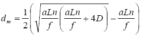 (5)
(5)
In this manner, by continuously controlling the hitting rate of milling bodies and the mill housing and by regularly measuring the chamber length and diameter, we can automatically determine the average diameter of milling bodies and its change in time upon the drift of the characteristic frequency.
The amplitude change of the mill housing vibroacoustic oscillations with the frequency of grinding bodies hitting the housing depends on the amount of materials in the milling chamber, which allows efficiently controlling the material flow into the chamber.
It is reasonable to read vibroacoustic oscillations directly from sensors installed on the drum mill journal bearing housing. A sensor with a preamplifier is shown in Figure 1:

Figure 1: Vibroacoustic sensor with amplifier. 1-base; 2-mounting bracket; 3-vibroacoustic sensor; 4-cable to transmit signals between sensor and amplifier; 5-amplifier; 6-cable with output signal and amplifier power supply cores; 7-protective housing.
A flow diagram of a device implementing automatic control of the ball mill level of filling with materials to be crushed is given in Figure 2.

Figure 2: Flow diagram of a device for automatic control of the ball mill level of filling with materials to be crushed.
Currently, the method to control the mill operation described above is implemented in tube mills (3 × 14) for wet milling of feed and dry crushing of hardburnt bricks in cement plants.
Since the operation control and monitoring method is based on the dynamics analysis of milling bodies, a foreign single body with a mass higher than that of milling bodies will be unambiguously identified by its surges of amplitude of vibroacoustic oscillations. In this manner, the control system allows providing objective information to the automatic mill control system for charging and additional charging, and issuing diagnostic signals in case of the following failures: armoring fall-out, foreign bodies getting into the crushing chamber together with the material to be crushed (teeth and crowns of excavator bucks, breaker parts, etc.); inter-camber grid destruction; mixing of milling bodies from adjacent chambers in multi-chamber mills.
The vibroacoustic control over the operation of drum and tube mills allows getting objective data on the current condition of milling equipment in concentration plants and in combination with the proposed methodological approaches it ensures active control over additional charging of the material and balls, and pilot control over quality characteristics of yielded milled products by means of purposeful changing of mill operating parameters. Early detection of equipment failures will ensure the integrated implementation of the maintenance and repair system adaptability principle and reduced operational expenses, which will finally result in reduced prime cost of finished products in concentration plants.
Copyright © 2024 Research and Reviews, All Rights Reserved