
ISSN (0970-2083)
ISSN (0970-2083)
A. Naymushin*, YU. Chertkov, M. Anikin and V. Boyko
National Research Tomsk Polytechnic University (TPU), 634050, Tomsk, Russian Federation
Received date: July 06, 2016; Accepted date: August 19, 2016
Visit for more related articles at Journal of Industrial Pollution Control
TResearch results of IRT-T reactor core modernization ways are shown in this article. This work describes current characteristics of reactor core and experimental facilities. Some possible ways of altering the configuration of the core during modernization are presented. For every variant of layout length of cycle and non-uniformity factors for energy release in reactor core were calculated. Alternative layout of reactor core which allows creating additional experimental channel near the lower border of the reflector with the same characteristics of thermal and fast neutron flux as in HEC-4.
IRT-T reactor, Neutron flux density, Reactor power, Energy release, Modeling.
IRT-T reactor has been successfully operating for about 50 years now (since 1967). Partial modernization of the reactor core (transition to the new IRT-3M fuel assemblies) took place in 1985 with the reactor power increase from 2 MW to 6 MW. Modernization of safety and control system of the reactor took place in 2005 (Varlachev et al., 2011).
In work of Naymushin A.G. horizontal cross-section of the reactor core, beryllium reflector and location of the experimental channels are shown (Naymushin et al., 2012). A beryllium trap was created around HEC-4 experimental channel during modernization in 1985. This trap allowed forming conditions for neutron transmutation doping of silicon ingots (NTD) of large diameter (up to 13 cm) and length (up to 70 cm). However, there was no work done to improve parameters of the reactor core ever since. For about 30 years, the reactor is operating in one mode with the same configuration of the reactor core and the same movement regulations of control rods.
The research reactor is a powerful source of fast neutrons and has certain technically implemented conditions required to carry out the experiments. These conditions include formation of horizontal beams of neutrons, organization of experimental volumes for placement of test materials samples or starting compositions with accumulated radionuclides, as well as creation of necessary conditions for irradiation and transportation of the samples and means of obtaining information.
Theoretical background (Klinov, 2003; Shchurovskaya et al., 2006) shows that altering these conditions could lead to increased performance of the reactor according to neutron flux density in the experimental channels. In the most powerful highflux reactors neutron flux density does not exceed 5·1015 cm-2-s-1 (at 100 MW power). In IRT-T reactor at 6 MW thermal power maximum thermal and fast neutron flux densities in major experimental channels reach the following values:
in vertical experimental channels:

in HEC-4 channel:

Thermal neutron quality index, which is a ratio of the maximum value of thermal neutron flux density to the reactor power, does not exceed 2.2·1012 cm-2-s-1MW-1 (for central vertical experimental channels), whereas for high-flux CM reactor it is 1.5 times higher.
Hence, there is a background for both probability and necessity of increasing the quality index of the reactor. Thereafter, it is probable to increase neutron flux density in the experimental channels of the reactor during its modernization as well as improve economic indicators of the reactor operation, in particular, to improve burn-up in spent and ejected fuel assemblies and to decrease annual demand for fresh fuel assemblies.
Ways of Increasing Neutron Flux Density
Considering the construction of IRT-T reactor it can be noted that the reactor core in its cross-section is a rectangle of 4x6 cells size or 286x429 mm, which is quite far from the ideal (square) size for this reactor (5x5 cells or 357x357 mm). Elongation of the reactor core leads to increased irregularity of neutron flux density distribution as well as energy release distribution resulting in inefficient use of nuclear fuel. One reason for this kind of form is present is the beryllium trap located in the center of the reactor core (2x2 cells or 143x143 mm). There are 2 central experimental channels in this trap (CEC-1 and CEC- 2, see Fig. 1). In them irradiation of molybdenum takes place. If these beryllium blocks are moved from center to periphery, its location and construction can be designed in such a way that technetium production rate at least will not decrease. However, the form of the reactor core will be more like a square, which can improve parameters of the reactor and increase quality index corresponding to thermal neutrons in the experimental channels.

Fig. 1: Established existing configuration of the reactor core: 8 – eight-tube IRT-3M fuel assembly; 6 –six-tube IRT-3M fuel assembly; Reactor cells with control and safety rods are highlighted dark grey. ÃÂõ – beryllium moderator with vertical experimental channel.
By changing location (and amount) of the central experimental channels neutron flux density in these channels can be increased as well as neutron spectrum can be changed.
Increase of neutron flux density may be achieved by simply raising reactor power from the existing 6 MW to 10 MW. However, this way is hindered by the fact that by doing so, temperature and heat flux density from the fuel elements will increase.
During normal operation mode of the reactor, the maximum values of heat flux density can reach up to 400 – 500 kW/m2 (average value – 300 kW/m2). IRT-3M fuel assembly’s passport data limit these values to 800 kW/m2. Safety factor of this parameter, which is the ratio of these values, is thus 1.6 – 2.0. If the minimum value of safety factor should not be lower than 1.2 the maximum value of heat flux density should not increase 650 kW/m2. In this case, by conserving movement regulations of control rods and configuration of the reactor core, the reactor power cannot be increased by more than 40 % – up to 8.5 MW. Herewith, irregularity factor of distribution of energy release over the reactor core volume becomes of high importance (existing value – 1.6). By optimizing configuration of the reactor core, the order of loading fresh fuel assemblies and movement regulations of control rods, the irregularity factor can be decreased (up to ~1.4 – 1.5) and both reactor power and neutron flux can be increased.
Another way of increasing neutron flux density while conserving reactor power is to increase specific density of energy release (Naymushin et al., 2012). This can be achieved by shrinking the volume of the reactor core or decreasing the number of fuel assemblies in it. For the reactor core generating neutrons which are consumed outside of it, neutron flux density in the reflector and in the central moderator hollow ät is proportionate to its production rate (power P) and inversely proportional to surface area S, through which these neutrons go. Surface area of the reactor core is in 2/3 proportion to its volume V while power, which is generated per volume unit is power density qv. Thus,
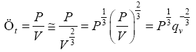
These calculations show that high specific density of power is a value of higher importance in terms of achieving high neutron flux density than the power. Therefore, by decreasing the number of fuel assemblies in the reactor core and locating them more closely, it can be expected that neutron flux density in the reactor experimental channels will increase. Wherein, the big central moderator hollow with beryllium will be a significant hindrance. It is required` to consider ways of reduction of the central beryllium blocks up to two and its shift from the center of the reactor.
Alternative Layout of Reactor Core
Different configurations of the reactor core with less number of fuel assemblies are considered in this paper with a purpose of increasing specific energy release and, therefore, neutron flux in the experimental channel of the IRT-T reactor.
Fig. 1 shows the existing configuration of the reactor core surrounded by the beryllium reflector.
Configurations of reactor cores of research reactors assembled based on IRT-3M fuel assemblies have different forms and number of loaded fuel assemblies. The IRT-MEPhI (Slivin et al., 2015) reactor has 16 fuel assemblies packed in 4x4 square surrounded by beryllium reflector. The VVR-CM (Uzbekistan) reactor can change configuration of the core from 4x4 square to 4x6 rectangle. The IRV-m2 reactor (Moscow district) has even more complex form of the reactor core and contains 17 fuel assemblies in a 5x5 square. The IRT-T reactor form is more similar to the CM-3 reactor, which has 32 fuel assemblies in a 6x6 square and its central beryllium trap (2x2 cells) is similar to the one of IRT-T.
Major irradiation experimental channels of the IRT-T reactor are HEC-4 located in reflector and two vertical channels in the central beryllium neutron trap. Thus, changing configuration of the reactor core will likely affect the vertical channels the most. Therefore, neutron flux and spectrum in them should not decrease when they are moved to another location.
Fig. 2-3 shows some possible ways of altering the configuration of the core during modernization. Suggested modifications contain 18 – 22 IRT-3M fuel assemblies.

Fig. 2: Possible ways of altering the configuration of the IRT-T reactor core with beryllium trap in center.

Fig. 3: Possible way s of altering the configuration of the IRT-T reactor core.
To estimate propagating properties of different configurations, fresh fuel was considered to be present in all reactor cells during the calculation. It was assumed that in eight-tube fuel assemblies there is 300 g of U235, and in six-tube assemblies – 262 g of U235. All regulation rods were ejected.
Use of fresh fuel in reactor cells allows estimating the effect of geometric features of different configurations of the reactor on its neutron-physical characteristics.
Fig. 4 shows energy release curves, which are the dependence of total change of reactivity margin for different configurations of IRT-T reactor core on energy release in the core.

Fig. 4: Reactivity margin for different configurations of the IRT-T reactor core vs. energy release in the core.
In modifications 1-2 there are 16 fuel assemblies and therefore, integral energy release during one cycle (26000 MWâÂÂh) is significantly lower than that, which corresponds to the established configuration (39000 MWâÂÂh). If using 18 fuel assemblies (modifications 3–4) energy release during one cycle shall not exceed the value corresponding to the established one, but was close to it.
If using 20 fuel assemblies (modifications 5, 6 and 8) energy release during one cycle shall exceed the value corresponding to the established one by more than 30 percent. Much more gain in energy release can be obtained by using 22 fuel assemblies (modifications 7 and 9).
Increase of energy release in these modifications allows increasing burn-up achieved in ejected spent fuel assemblies and economic indicators of the reactor.
Therefore, when considering possible ways of modernization it is required to choose from these options. Modification 6 – is a tight setting of 20 fuel assemblies in a 5x4 cell rectangle and has no moderator hollow. In this case, central vertical experimental channels may be located in beryllium blocks of the first row of beryllium reflector.
Modification 6 allows creating additional experimental channel near the lower border of the reflector with the same characteristics of thermal and fast neutron flux as in HEC-4.
From the standpoint of uniformity of energy release distribution, modification 6 has the least irregularity factor. While it ranges from 1.20 – 1.25 in all other modifications, in this one it is ÃÂq = 1.13. This is because the central beryllium neutron trap has the most effect on irregularity of energy release distribution. This trap is missing in modification 6 or is moved outside the reactor core in the first row of the reflector. The value of thermal neutron flux density in cells of the first row of beryllium blocks of the reflector is close to the value of one observed in the existing central beryllium neutron trap (Slivin et al., 2015).
The existing modification of the IRT-T reactor core differs from the similar IRT or VVR type reactors and is not the optimal solution both from the standpoint of achieving higher values of neutron flux and, a fortiori, economic expenses required for neutron production.
Altering the existing configuration of the reactor core allows achieving gain in neutron flux density in the experimental channels of the reactor. By implementing this change, fuel burn-up in spent fuel assemblies can be significantly increased while annual demand for fresh fuel assemblies will be lower.
This work was performed on the unique scientific IRT-T equipment and financially supported by Government represented by the Ministry of Education and Science of the Russian Federation (RFMEFI59114X0001).
Copyright © 2024 Research and Reviews, All Rights Reserved