
ISSN (0970-2083)
ISSN (0970-2083)
Evgeniy Vitalievich Shishkin* and Pavel Vitalievich Shishkin
St. Petersburg Mining University 199106, St. Petersburg, Line 21 Vasilyevsky Island, bld. 2, Russia
Received date: 06 May, 2017; Accepted date: 08 May, 2017
Visit for more related articles at Journal of Industrial Pollution Control
This paper studies the effect of milled material on the dynamics and stability of the vibration gyratory-cone crusher where the body and milling cone oscillations are excited by two unbalance vibration exciters installed on the machine body. The laws of induced oscillations of the active crushing members with account for the motion viscous resistance as well as the equation of the power balance in the machine operating mode and the equation for determining the specific coefficient of equivalent viscous resistance, n, were deduced. The condition of synchronous existence of in-phase vibration exciter rotation mode and steady operation of the crusher was formulated, which imposes certain constraints on the maximum power of the motors in the machine operating mode used for material crushing.
Vibration gyratory-cone crusher, Power balance equation, Maximum power, Viscous resistance, process duty
The vibration gyratory-cone crusher developed in the Research and Engineering Corporation MEKHANOBR-TEKHNIKA (Vaisberg, et al., 2004) is developed for milling various types of natural and man-made mineral raw material. This machine has such advantages as a high degree of crushing and insignificant content of \fine grains in the crushed material, which in its turn has high practical value for the products manufactured of this material. The crusher consists of a soft reinforced body and a crushing cone attached to the body by means of special helical spring packs. At that, the cone has only one translational degree of freedom. The crusher is set into motion by a pair of self-synchronized inertial vibration exciters installed on the body. With such installation of the vibration exciters, the selfsynchronization margins turn out to be sufficiently high and weakly depend on the machine operation mode. At that, the crusher dynamic scheme is symmetrical and balanced. Apart from this, the fact that no stiff kinematic links between two selfsynchronized vibration exciters are present makes the machine considerably easier to maintain and reliable in operation.
The paper considers the effect of the process duty (the material milled in the crushing chamber) on the stea diness of the synchronous-counterphase motion of the body and crushing cone in the operation mode by means of introducing linear-viscous damper between the crushing agents. It seems that such a method of accounting for the effect of the process duty, as an equivalent viscous resistance against the active member oscillations, on the dynamics of a shock-vibrating machine (vibrating grizzly) has been proposed and successfully used in practice (Barzukov Vaisberg, et al., 1978), and then developed in a monograph (Vaisberg, 1986)
Crusher oscillation equations
The dynamic flowchart of the machine considered in this paper is shown in Fig. 1. The crusher body 1, as well as the crushing cone 3, attached to the body by means of the special helical spring pack 2, can be considered as absolutely solid bodies which move translationally (straightforwardly) in the operating mode. At that, the crusher body has rubber-in-shear mounting 4 with vanishingly small rigidity. The inertial vibration exciters 5, located inside the body (load-bearing body) are unbalanced rotors rotated by two independent asynchronous motors. The axes of the vibration exciters are perpendicular to the plane on which the crusher moves.

Fig. 1 Dynamic flowchart of the vibration gyratory-cone crusher.
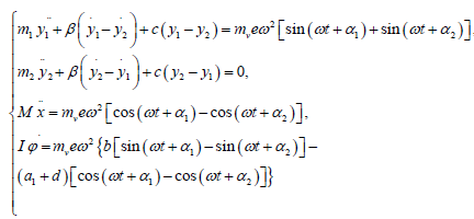
The dynamics of the considered machine is studied in the paper (Shishkin and Kazakov, 2015) where the equations of induced crusher oscillations are obtained in the form of the second-kind Lagrange equation. At that, the resistance against the crusher body and cone oscillations proportional to the first degrees of the velocities of their gravity centers were accounted for (this is how the presence of material in the crushing chamber was taken into account). It is extremely important to take into account the influence of the crushed material on the stability of the operating mode or determining the conditions of existence and steadiness of the body and crushing cone synchronous-counterphase motion in this mode. Therefore, the model of a machine with linearviscous damper between two crushing agents was used for the study of this issue. If we suppose that the vibration exciter rotors rotate smoothly with a preliminarily unknown synchronous angular rate ω and phase shifts α1 and α2, that is,
φ 1 = ωt + α1, φ2= ωt + α2 (1)
then the equations of the crusher small oscillations under the effect of harmonic perturbing forces will be written as follows:
 (2)
(2)
Here, as previously [4], the following designations are adopted: Cxy– fixed Cartesian reference system; the point C is the common gravity center of the system if the masses of all bodies m1 and m2, as well as the masses of the rotors (vibration exciters) mv1 and mv2 (mv1 = mv2 = mv) are taken into account; y1 and y2 are the coordinates of the gravity centers of the body, C1, and the crushing cone, C2; x and φ are the coordinate of C and the rotation angle of the body 1 and 2 system as a single solid body, measured counterclockwise; φ1 and φ2 are the rotation angles of the eccentricity-vectors of the exciters relative to a fixed axis Cx, measured in opposite directions: φ1– counterclockwise, and φ2 – clockwise; M = m1+ m2 + 2mv is the total mass of the crusher; α1 and α2 are vertical distances between the system gravity center and the body and crushing cone gravity centers, respectively, in the position of the machine static equilibrium; b and d are, respectively, horizontal and vertical distances between the axes of the exciters and the body gravity center; e is the unbalances eccentricity (distance from the rotation axis of the exciters and the unbalance gravity center) of vibration exciters; c is the helical spring pack rigidity; β is the coefficient of equivalent viscous resistance; I is the equivalent central torque of the system inertia; determined under the formula:
I= I1+I2+ma2
where I1and I2 are the central body and crushing cone inertia torques;  is the reduced mass of the considered two-mass system, a is the vertical distance between the body and the cone mass centers in the position of the machine static equilibrium.
Direct solving the system of equations (2) at arbitrary initial values of α1 and α2 allows obtaining the laws of induced oscillations of the body and crushing cone in the following form:
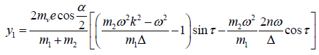 (3)`
(3)`
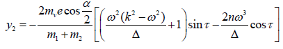
Where
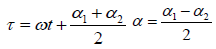
 (4)
(4)
Here  is the proper frequency of summary oscillations of the considered two-mass system,
  is the specific viscous resistance coefficient.
Power balance equation
Now let us consider the motion of the vibration exciters (unbalances) (Blekhman, 2013; Blekhman, 1971; Blekhman, 2000; Fidlin and Drozdetskaya, 2015; Sperling, et al., 1997; Sperling, et al., 2000). We assume that the torques L1 and L2 of the electric motors, as well as the torques in bearings R1 and R2, act along the coordinates φ1 and φ2. Let us consider that the torques are the given functions of unbalance angular velocities, φ1 and φ2. Then, the equations of the rotation of vibration exciters in the form of the second-kind Lagrange equations will have the following form:
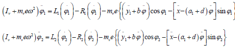 (5)
(5)
where Iv is the central torque of the unbalance inertial. Then we assume that the rotors of the exciters rotate almost smoothly, and the links between are weak. To determine the synchronous angular velocity ω and the phase shift differences, α1 − α2 , the right parts of the motion equations (5) of the exciters shall be averaged for the period  according to the method of small parameter. At that, the expressions (1) and (3) shall be put under the integrals. In the result of averaging, we get:
Pi≡ L(ω) – R (ω) − Wi=0, i=1,2, (6)
where the quantities
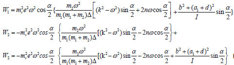 (7)
(7)
are referred to as vibration torques that characterize the averaged impact of the torque type which is transmitted from one exciter to the other via small oscillations of the body (bearing body).
The system of two transcendental equations (6) allows the solution α=0, which corresponds to the synchronous-sinphase mode, for the determination of unknown ω and α. In fact, after the value α=0 is substituted in the equations (6), we get only one equation for the determination of ω:
L(ω) = R(ω) +W(ω) (8)
where the quantity
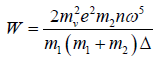 (9)
(9)
equals the period-average vibration torque that constrains the rotation of the exciter rotors in the synchronous-sinphase mode.
By multiplying the equation (8) by 2ω we get:
2ωL =2ωR+2ωW (10)
This relation has the form of the power balance equation in the system.
Let us introduce the designation:
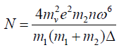
N = 2ωW = 2ω (L – R) (11)
Note that the averaged power N=2ωW characterizes the useful power expenditure for crushing the material in the operating chamber. It is important that the value of the equivalent coefficient of viscous resistance β (or n) shall be adopted from the equation (10) (or (8)). For this purpose the average motor power 2ωL, as well as the power 2ωR that characterizes the power loss in bearings, shall be experimentally determined.
After the expression (9) is substituted in the equality (11), the power balance equation in the crusher operating mode gains the final form:
 (12)
(12)
This relation can be considered as the equation for determining the specific coefficient of the equivalent viscous resistance, n. At that, the value of the power, N, as well as the synchronous angular velocity ω, shall be determined experimentally for the given crusher operation mode. The corresponding equation, following from the expression (4), is a square root and has the following form:
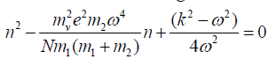 (13)
(13)
The solution of the quadratic equation (13) has the form as follows:
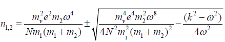 (14)
(14)
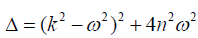
In the case of the symmetrical resonance (ω=k), the specific coefficient of the equivalent viscous resistance cannot equal zero. Therefore, only the sign “+” in front of the radical has the physical sense. Apart from this, the quadratic discriminant (14) must be positive. The corresponding inequality is written in the following form solved for N:
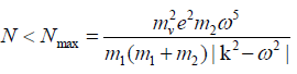 (15)
(15)
The inequality (15) shall be satisfied to secure the synchronous-sinphase mode of the vibration exciter rotation in the crusher. In other words, the inequality (15) allows determining the summarized maximum motor power in the machine operating mode spent for the material crushing.
From (8) it follows that the initial phase ÃÂ, the value of which for sinusoidal component A sin(ωτ + ÃÂ) is unknown, influences the formation of the amplitudefrequency spectrum. This influence is by way of component 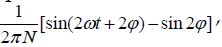 and is reduced to exposing formed spectrumΦ = Φ(t,ω,ÃÂ ) to pulses with frequency 2ω, and offsetting it by value sin 2φ, which, due to multiplier
  decrease their values with time.
The presence of component 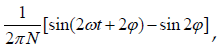 where phase value ÃÂ is unknown, affects subsequent analytical calculations based on formula (8), for example, hampers calculation of amplitudes A with required precision.
The influence of component on the value of spectrum ä= ä(t,ω,φ), which is formed based on formula (8), may be reduced by increasing time interval [0, t], i.e. the time of forming the amplitude-frequency spectrum. With time t that corresponds to N periods of the sinusoidal component, the influence of this component on the value of the formed amplitude-frequency spectrum, according to (11), will not exceed value 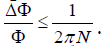 This allows, through choosing time of spectral analysis t, to reduce the influence of initial phases on the result of calculation by formula (8) to the desired values. So, for instance, if for forming an amplitude-frequency spectrum at frequency ω, time t is allocated, which corresponds to N = 16 periods, the uncertainty introduced by the influence of the initial phase of the harmonic on the value of the formed spectrum at this frequency will not exceed
  Φ . Accordingly, if amplitudes A are to be calculated with the use of formula (8) with the relative error not exceeding δ ≤ 0.01, then, in accordance with formula (12) for forming the spectrum, it is necessary to allocate time that corresponds to 16 periods.
The performed theoretical study allows estimating the effect of crushed material on the dynamics and steadiness of the vibration gyratory-cone crusher operating mode. In particular, the derived formula (14), when experimental data is used, enables determination of the numerical value of the specific equivalent viscous resistance coefficient, n, and under the condition that the inequity (15) is satisfied, in the machine designed under the considered scheme, the synchronous sinphase rotation of vibration exciters is realized required for the crusher efficient operation.
Copyright © 2024 Research and Reviews, All Rights Reserved