
ISSN (0970-2083)
ISSN (0970-2083)
A. Yerrayya, P.V. Suresh*
Department of Chemical Engineering, National Institute of Technology, Warangal-506004, India.
Received date: March 14, 2016; Accepted date: April 19, 2016
Visit for more related articles at Journal of Industrial Pollution Control
The continuous increase in the demand for quality power necessitates the operation of power plants in most energy efficient manner. This requires exergy analysis in addition to the energy analysis for any plant. In this study, a 50 MW syngas fuelled power plant with chemical looping combustion (CLC) implementation, where a conventional combustion chamber is replaced by a two reactor setup-fuel reactor followed by air reactor, is considered. An exergy analysis by means of exergy efficiency and exergy destruction efficiency for different units in this plant is presented. The analysis concludes that any developments/changes to be carried out in the plant to improve the overall thermal efficiency of the plant have to be directed towards the fuel reactor as the exergy destruction efficiency of the fuel reactor is found to be more among all other units. This study employs an Aspen Plus model to investigate the effect of air mass flow rates on the thermal efficiency
Exergy, Chemical looping combustion, Syngas, Power plants, Exergy efficiency
Increased concentration of carbon dioxide (main constituent of the greenhouse gases) in the atmosphere, released by the combustion of fossil fuels is one of the major environmental threats of the present world. Usage of fossil fuels is inevitable and it will continue to be the primary source, as energy demand is increasing exponentially day by day (Figueroa, et al., 2008). Using fossil fuels without CO2 emissions is possible by two ways-separation of CO2 and storage. Separation can be done by using different technologies such as post-combustion, pre-combustion and oxy fuel combustion. All these techniques have a common disadvantage of high energy penalty for separation of gases (in order to obtain the CO2 in pure form). This energy penalty can be overcome by using chemical looping combustion technique. It is an energy efficient technique to separate CO2 from the flue gases, with the aid of an oxygen carrier.
Chemical looping combustion (CLC) system consists of two reactors-one is air reactor and other is fuel reactor. These reactors are usually operated as interconnected fluidized beds (Adanez, et al., 2012; Erlach, et al., 2011). Nickel oxides (NiO) are generally used as oxygen carriers for syngas fuel. In air reactor, Ni is entrained in a fluidized bed with air as the fluidizing agent, where Ni reacts with oxygen to produce NiO according to the Eq. (1). NiO is then separated from N2 and transferred to the fuel reactor. In fuel reactor, NiO reacts with synthesis gas to produce CO2 and H2O according to the Eqs. (2) and (3). Reduced Ni is recycled back to air reactor. This process continues and pure CO2 stream would be available after the condensation of water. A schematic representation of Chemical looping combustion process is shown in Fig. 1.

Fig 1. Principle of chemical looping combustion
In air reactor
Ni + 0.5O2 → NiO (1)
In fuel rector
CO + NiO → CO2 + Ni (2)
H2 + NiO → H2O + Ni (3)
Overall reaction
CO + H2+ O2 → CO2 + H2O (4)
The demand for quality power production is increasing continuously and this imposes the power plants to operate in most energy efficient manner. Most of the power plants are generally designed by the energy performance criteria based on first law of thermodynamics. This energy analysis gives only quantitative results, while the exergy analysis which is based on the maximum useful work, presents qualitative results of the actual energy conversion. The exergy of a material stream can be decomposed into thermal, mechanical and chemical components. Physical exergy which is sum of thermal and mechanical exergies can be obtained from entropyproduction flow, whereas chemical exergy is the maximum work that can be obtained when the considered system is brought into reaction with reference substances present in the environment.
(Bilgen et al., 2008) calculated the chemical exergy of various fuels by using equations given in the literature to detect and to evaluate quantitatively the effect of irreversible phenomena which finally leads to the thermodynamic imperfection of the processes. (Wang et al., 2013) presented the energy and exergy analysis of the hydrogen fueled power plant with inherent CO2 capture based on calcium looping process. They concluded in their analysis that the combustion chamber and regenerator were responsible for large exergy destructions. An analysis on the energetic performance of gas turbine based cycles with chemical looping combustion and a comparison with similar systems with conventional combustion, when syngas from gasification of biomass is used as fuel and iron oxides as oxygen carrier are studied by (Jimenez Alvaro et al., 2014). They further presented the results about the energetic performance of an IGCC plant based on CLC with CO2 sequestration (Jimenez Alvaro, et al., 2015; Kaushik et al., 2011) carried out energy analysis of IGCC with CLC, based on the first law of thermodynamics and also performed exergy analysis based on the conservation of mass and degradation of the quality of energy along with the entropy generation to complement the energy analysis. (Al- Doori et al., 2012) performed an exergetic analysis for a Baiji plant with a gas-turbine of capacity 159-MW and concluded that the exergy destruction taking place in the combustion chamber was high and the inlet temperature of turbine had an effect on both the exergetic efficiency and the exergy destruction in the plant. (Erlach et al., 2011) studied the CLC integrated IGCC theoretically using Aspen Plus and compared the results with a conventional IGCC with precombustion carbon capture by physical absorption. (Mukherjee et al., 2015) compared the characteristics of three CO2 capture technologies such as CLC, pre-combustion and oxy-fuel combustion with a conventional IGCC plant without CO2 capture by performing the energy analysis.
Even though many studies are available on the energy analysis of different power plants including IGCC and CLC integrated plants, only few studies are available on the exergy analysis of CLC integrated power plants and on the effects of key operating parameters on the overall plant performance. In this work, an attempt has been made to perform an exergy analysis of a 50 MWth syngas fuelled power plant integrated with CLC utilizing Nickel Oxide (NiO) oxygen carrier. It is necessary to conduct this kind of studies to run the CLC integrated power plants with inherent CO2 capture in the most economic and effective way. The present study focuses on determining the effect of air flow rate and fuel flow rate on the overall thermal efficiency of the plant and exergy destruction losses in different key units involved in the power plant and identifying the units with highest exergy destruction. The units with lower exergy efficiencies or higher exergy destruction losses will be the culprits in lowering the overall thermal efficiency of the plant. Hence, the outcome of the study would be useful in getting the information on the possible units to be given attention in order to increase the overall plant performance.
The term Exergy refers to the Greek words ex (external) and ergos (work). The term is also described as Available Energy or simply Availability. Szargat et al., defined exergy as: “Exergy is the amount of work obtainable when some matter is brought to a state of thermodynamic equilibrium with the common components of its surrounding nature by means of reversible processes, involving interaction only with the above mentioned components of nature”, in short it is defined as the maximum useful energy that can be obtained from the system when it proceeds from a particular state to the state of equilibrium with its surroundings. Gundersen et al., classified exergy for PVT systems as shown in Fig. 2.

Fig 2. Exergy classification
In this study, exergy transfer associated with material streams is considered in two ways: physical exergy transfer (thermal and mechanical) and chemical exergy transfer. Mechanical components of exergy transfer such as potential and kinetic exergies are neglected (Szargut et al., 1988).
Physical Exergy
Physical exergy is the maximum useful work obtained by passing unit mass of a substance from general state (T, P) to environmental state (T0, P0) (Kotas 1995; Javad et al., 2005; Chand et al., 2005). It can be considered as two parts- temperature based and pressure based parts. Temperature based part deals with the temperature change from T to T0 at constant pressure whereas pressure based part deals with the pressure change from P to P0 at constant temperature.
Physical exergy can be calculated as:
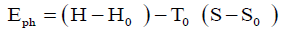 (5)
(5)
For solids and liquids, the above equation can be expressed as follows (assuming a constant specific heat Cp):
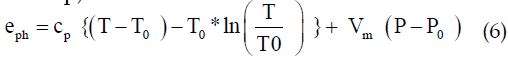
Where, Vm is the specific volume at temperature T0.
Chemical Exergy
Chemical exergy is defined as the maximum useful energy, which would be attained by passing from the environmental state to dead state.
Chemical exergy of pure component gases at a reference state/dead state can be calculated as follows (Jimenez Alvaro et al., 2015):
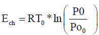 (7)
(7)
Where, P00 is the partial pressure of the component in the reference state/dead state.
The chemical exergy for mixtures can be calculated as follows (Chand et al., 2013)
 (8)
(8)
Where, xi is the mol fraction of the ith component, R is the molar gas constant and γi is the activity coefficient. For ideal solutions the activity coefficient is equal to one.
For many fuels (coal, oils, and petrol etc.) the chemical structure is unknown. The chemical exergy for these fuels can be estimated on the basis of lower heating value (LHV). The relation between the LHV and the chemical exergy (Chand et al., 2013) is
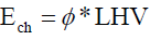 (9)
(9)
Where, ÃÂÃ⢠can be calculated by formulae based on the atomic composition. For different fuel oils and petrol, ÃÂÃ⢠varies between 1.04 and 1.08.
Exergy Destruction Efficiency and Exergy Efficiency
According to first law of thermodynamics, energy is never destroyed during a process; it changes from one form to another form, so the total energy is conserved. In contrast, exergy is not conserved and destroyed by irreversibility of a process due to increase in entropy. Exergy is lost, when the energy associated with a material or energy stream is rejected to the environment.
Exergy destruction efficiency (yD) is defined as the ratio of the rate of exergy destruction (ED) in a system to the input exergy rate to the system (EF, total) (Tsatsaronis et al., 2007).
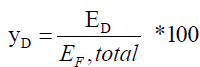 (10)
(10)
The rate of exergy destruction is the exergy loss in a system which can be calculated by subtracting the output exergy from input exergy.
The exergy efficiency is defined as the ratio of the rate of exergy out (Eout) to the rate of exergy in (Ein).
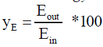 (11)
(11)
In chemical looping combustion, direct contact between fuel and air will not happen, and the combustion takes place separately in two reactorsair reactor (AR) and fuel reactor (FR) as shown in the flow sheet in Fig. 3. This system is simulated using Aspen Plus v8.1. Hence, the nomenclature of the models used for the present study are based on the Aspen Plus, which are widely used by different researchers in other studies (Wang et al., 2013; Al Doori., 2012; Meng., 2015; Smith et al., 2005). In these simulations, MIXCISLD is used as the stream class, which contains MIXED stream and CONVENTIONAL SOLIDS. RSTOIC reactors are used to model the air and fuel reactors in this study, as they can handle reactions that occur independently in a series of reactors and provide product selectivity and heat of reaction calculations. Gas-solid separator is modeled using component separator model in Aspen. All these models in Aspen plus flow sheet are solved in a sequential modular approach, where the mass and energy balance equations for different units are solved sequentially using tear streams in case of recycle streams. This involves multiple pass calculations for solving a system of linear/nonlinear equations to converge the tear stream. Selectivity analysis has been carried out for optimizing the values of solids flow rate as well as air flow rate. The temperature in the air reactor is fixed as 1200°C as it is usually limited by the melting point temperature of oxygen carrier (NiO, in this case). So, air reactor is modeled in isothermal condition, while the fuel reactor in adiabatic conditions. The air reactor outlet contains N2 and un- reacted oxygen and these are expanded in a gas turbine for power production. The entire process modeled in Aspen Plus is shown in Fig. 4.

Fig 3. Flow sheet for chemical looping combustion

Fig 4. Modelled chemical looping combustion in Aspen plus.
The input, output, work and heat integration streams can be distinguished by the color of the lines as shown in Fig. 4. Green colour line represents the input and output streams, pink color line refers to heat integration stream and red colour represents work stream. Syn gas flow rate used in these simulations to produce 50 MW is 4 kg/s. Values of various other parameters considered for the present study are listed in Table 1 [20].
| Parameter | Value |
|---|---|
| Fuel input | 50 MW |
| Atmospheric conditions | 25°C, 1.013 bar |
| Air reactor temperature | 1200°C |
| Pressure | 20 bar |
| Syngas composition at fuel reactor inlet | 29.3% H2, 50.7% CO, 6.9% CO2, 12.6% H2O, 0.45% N2 |
| Fuel conversion efficiency | 98% |
| Ni conversion rate in air reactor | 98% |
| Compressor efficiency | 85% |
| Isentropic efficiency of turbine | 88% |
The simulated results of the units are further used to calculate the exergy efficiencies and exergy destruction efficiencies of various units as discussed above.
Sensitivity analysis of air flow rate on the efficiency of the syngas fuelled power plant with CLC has been studied and is presented below. The exergy efficiency and destruction efficiency are also calculated for the plant and presented in this section.
Effect of air flow rate on the performance of thermal efficiency
Fig. 5 shows the effect of air flow rate on overall thermal efficiency of the syngas fuelled power plant. Overall thermal efficiency of the plant has been calculated as the ratio of net power generated (=total power generated–power consumption) to the total thermal energy of the input fuel (=flow rate × LHV). From Fig. 5, it can be observed that the efficiency of the plant increases to a maximum value and then decreases with increase in air flow rate. The net power generated depends on the temperature of the streams coming out from the air reactor which are going to the gas turbine. This in turn depends on the temperature of the air reactor. An increase in air flow rate increases the air reactor temperature to a maximum value and then reduces gradually. The initial increase could be due to the oxidation of metal oxides from Ni to NiO. As the air flow rate increases, oxidation of solids also increases and since the oxidation is an exothermic reaction, the temperature also increases. But after the solids are completely oxidized, the excess amount of air provides a cooling effect as it takes sufficient amount of heat to get heated up. This causes a decrease in air reactor temperature, which further reduces the net power generated, hence the efficiency of the plant. The optimum air flow rate of 22 kg/s corresponding to the peak thermal efficiency of about 31.2% has been chosen for further analysis.

Fig 5. Efficiency vs Air flow rate
Exergy efficiency (yE) and Exergy destruction efficiency (yD) of different units in the CLC integrated syngas fuelled power plant.
The main difference between energy and exergy is that energy is conserved whereas some exergy is destroyed. Exergy destruction can take place due to the irreversibilities of the process (heat transfer, chemical reaction, mixing etc.) or it can be lost due to leakage (release in purge, bleed streams or cooling water). The input and output exergies for each unit have been calculated. From these values, efficiency is calculated in order to understand the total exergy utilizable to the system. An efficiency based on total exergy is calculated considering only the irreversibility of the system neglecting the losses.
The physical and exergy values have been calculated using the eq. 5 and eq. 8. The standard values of enthalpy and entropy for different components involved in the process are presented in Table A1 of Appendix-1 (Smith et al., 2005). These values are used to calculate the standard enthalpy and entropy of the mixture of gases, which are further used to calculate the physical exergy values. The standard chemical exergy values (Smith et al., 2005) used for different components and presented in Table A2 of Appendix-1. These are used to calculate the chemical exergy of mixture streams from environmental state to reference state.
The total exergy is calculated from the sum of physical and chemical exergy values. These are further used to obtain the exergy efficiency and exergy destruction efficiency for each unit using eq. 11 and 10 respectively. The calculated exergy efficiency and exergy destruction efficiency values are listed in the following Table 2.
| S. No. | Components | Exergyefficiency (%) | Exergy destruction efficiency (%) |
|---|---|---|---|
| 1 | Compressor | 81 | 19 |
| 2 | Mixer | 99 | 1 |
| 3 | Air reactor | 90 | 10 |
| 4 | Seperator1 | 98 | 2 |
| 5 | Fuel reactor | 65 | 35 |
| 6 | Seperator2 | 67 | 33 |
| 7 | Turbine | 82 | 18 |
Table 2. Exergy efficiency Vs. different components in CLC system
The values of exergy efficiency and exergy destruction efficiency of different units in CLC integrated syngas fuelled power plant are plotted in Fig. 6. It can be observed that, the exergy efficiency of compressor and turbine are more compared to that of fuel reactor. Of all the units, it can be observed that the exergy efficiency is less for the fuel reactor and separator 2. Exergy efficiency in fuel reacor could be low due to high syngas flow rate, which has high quantity of exergy of CO.

Fig 6. Exergy efficiency (yE) and exergy destruction efficiency (yD) of different units
Fig. 7 represents the distribution of total exergy destruction efficiency of different units. This also shows that fuel reactor has high destruction efficiency. Hence, the exergy analysis presented through Figures 6 and 7 help in identifying the units, where the maximum exergy is destroyed. This gives a direction to focus on the units which cause high exergy destruction efficiency, in order to increase the overall plant thermal efficiency. The study helps in identifying the units to be improved in future to operate the plant efficiently and economically.

Fig 7. Exergy destruction efficiency (yD) of different units
Conclusions
Exergy analysis is performed for chemical looping combustion integrated 50 MW syngas fuelled power plant. Thermal efficiency of the plant is found to be 31.2%. Effect of air flow rate on overall thermal efficiency of the syngas fuelled power plant is analyzed. An initially increasing graph followed by decreasing tendency indicates the necessity of using optimum flow rate of air, which was calculated and found out to be 22 kg/s for 4 kg/s of fuel. Exergy destruction is observed to be more in fuel reactor.
From the exergy efficiency and exergy destruction efficiency analysis, it can be concluded that the overall plant efficiency can be improved by focusing the attention on fuel reactor than any other units.
Authors acknowledge the Science and Engineering Research Board (SERB), Government of India for supporting this work through a sponsored project (SB/FTP/ETA-0421/2013).
Exergy is defined as the maximum work that may be achieved by bringing a system into equilibrium with its environment. Any system, which is not in equilibrium with its environment, will have some exergy. Table A1 presents the standard values of enthalpy and entropy for different components (Smith et al., 2005) involved in the process, which are used to calculate the standard enthalpy and entropy of the mixture of gases. The standard chemical exergy values (Smith et al., 2005) for different components are presented in Table A2.
The chemical exergy values of various components as listed in Table A2 are used to calculate the chemical exergy of mixture streams from environmental state to reference state.
Copyright © 2026 Research and Reviews, All Rights Reserved