
ISSN (0970-2083)
ISSN (0970-2083)
1Department of Chemistry, Adhiyamaan College of Engineering, Hosur 635 109, India
2Department of Chemistry, St. Joseph’s College, Trichy 620 002, India
Received: 23 September 2011 Accepted: 05 December 2011
Visit for more related articles at Journal of Industrial Pollution Control
In the present investigation an attempt is made to treat organic pollutant present in the textile effluent using an electrochemical treatment technique. Experiments are carried out in a batch electrochemical cell covering wide range in operating conditions. Due to the strong oxidizing potential of the chemicals produced, the effluent COD is reduced substantially in this treatment technique. The influence of effluent initial concentration, pH, supporting electrolyte concentration and the anode material on pollutant degradation has been critically examined. It further attempts in the present investigation to reuse the treated polluted water for dyeing purpose. Several cycles (eleven times) of dyeing operations have been performed with the treated textile polluted water and the dye uptake and water quality have been critically examined at each cycle of dyeing process. The results indicates that the electrochemical method is a feasible technique for treatment of textile polluted water and electrochemically treated polluted water can be effectively reused for dyeing application.
Electrochemical oxidation, Textile effluent, Polluted water treatment, Reuse
The day-to-day human activities and industrial revolution have been influening the flow and storage of water and the quality of available fresh water. Many industries like textile, refineries, chemical, plastic and food-processing plants produce polluted waters characterized by a perceptible content of organics (e.g. , phenolic compounds) with strong color. For example, a typical textile dyeing process consists of desizing, scouring, bleaching, dyeing, finishing and drying operations. Except the last two stages, each operation is associated with rinsing step, requires large amount of water. In general, textile industries generate effluent at an average of 100–170 L kg-1 of cloth processed, which is characterized by strong color, high COD with wide variation in pH (Rajagopalan, 1989 and Panchiao, 1994).
Conventionally effluents containing organics are treated with adsorption, biological oxidation, coagulation, etc. Though the conventional methods have individual advantages, they are lacking effectiveness if applied individually. For example, biological treatment is the most efficient and economic way of reducing the environmental impact of the industrial effluents containing organic pollutants, but this technique is time consuming and cannot be employed for textile effluent, as textile effluent is recalcitrant to biodegradation. On the other hand, the physical adsorption is expensive and difficult for adsorbent regeneration. Further, biological and chemical methods generate considerable quantity of sludge, which itself requires treatment. Due to the large variability of the composition of textile polluted water, most of the traditional methods are becoming inadequate (Hao et al., 2004 and Sakalis et al., 2005).
As environmental regulations become stringent, new and novel processes for efficient treatment of various kinds of polluted water at relatively low operating cost are needed. In this research various alternative processes, such as electrochemical technique, wet oxidation, ozonization, photocatalytic method for the degradation of organic compounds have been tried. Among these advanced oxidation processes, the electrochemical treatment has been receiving greater attention in recent years due to its unique features, such as versatility, energy efficiency, automation and cost effectiveness (Gutierrez et al. 1999 and Lorimer et al., 2001).
In electrochemical technique, the main reagent is the electron, called ‘Clean Reagent’ degrades all the organics present in the effluent without generating any secondary pollutant or by-product/sludge. The electrochemical technique offers high removal efficiencies and has lower temperature requirements compared to non-electrochemical treatment. In addition to the operating parameters, the rate of pollutant degradation depends of the anode material. When electrochemical reactors operate at high cell potential, the anodic process occurs in the potential region of water discharge, hydroxyl radicals are generated (Simond et al., 1997). On the other hand, if chloride is present in the electrolyte, an indirect oxidation via active chlorine can be operative (Kotz et al., 1991 & Szpyrkowicz et al. 2005). Naumczyk et al., (1996) have demonstrated several anode materials, such as graphite and noble metal anodes successfully for the mediated Oxidation of organic pollutants. Comninellis, (1994) experimented anodic oxidation of phenol in the presence of NaCl using tin oxide coated titanium anode and reported second order kinetics for the degradation of phenol at the electrode surface. Fernandes et al. (2004) studied the degradation of C.I. Acid Orange 7 using boron-doped diamond electrode and reported more than 90% of COD removal. Anastasios et al. (2005 )demonstrated 94% dye removal using a pilot plant electrochemical reactor for textile polluted water treatment.
The use of new anodic materials like boron-doped diamond (BDD) has also been reported in recent years as BDD electrodes present additional properties including high resistance to corrosion, high thermal stability, hardness, good electrical conductivity, etc. Panizza et al., (2001) have demonstrated 2-naphthol oxidization in acid media using synthetic BDD thin film electrodes and reported complete incineration of 2- naphthol. Bellagamba et al., (2002) reported on electro combustion of polyacrylates (PA) under galvanostatic conditions using BDD anode at various current densities and in a wide range of PA concentrations. Canizares et al., (2005). Studied the electrochemical oxidation of several phenolic aqueous pollutants using bench-scale electrochemical flow cell with boron-doped diamond anode. Complete mineralization of the waste was obtained in the treatment of phenols not substituted with chlorine or nitrogen. The authors reported that efficiencies of the process depend strongly on the concentration of organic pollutants and on their nature, and not on the current density, at least in the operation range studied.
The reported works are intended to treat the textile polluted water to a level that meets the discharge standards of pollution control board. However, due to dwindling water supplies, increasing demand of the textile industries and stringent pollution control board regulations, a better alternative is to further elevate the quality of treated polluted water to a standard where it can be reused. Though extensive work has been reported on various treatment techniques, the literature on reuse of treated polluted water is scarce. The objective of the present work is thus to study the electrochemical treatment of textile effluent using graphite, Pt, Stainless Steel (304) and Pb/ PbO2 anodes and reuses the treated polluted water for dyeing process.
Theory
The mechanism of electrochemical oxidation of polluted water is a complex phenomenon involving coupling of electron transfer reaction with a dissociate chemisorptions step. Basically two different processes occur at the anode; on anode having high electro-catalytic activity, Oxidation occurs at the electrode surface (direct electrolysis); on metal oxide electrode, oxidation occurs via surface mediator on the anodic surface, where they are generated continuously (indirect electrolysis). In direct electrolysis, the rate of oxidation is depending on electrode activity, pollutants diffusion rate and current density. On the other hand, temperature, pH and diffusion rate of generated oxidants determine the rate of oxidation in indirect electrolysis. In indirect electro-oxidation, chloride salts of sodium or potassium are added to the wastewater for better conductivity and generation of hypochlorite ions (Rajeshwar et al., 1997). The reactions of anodic oxidation of chloride ions to form chlorine is given as
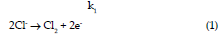
The liberated chlorine form hypochlorous acid
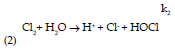
and further dissociated to give hypochlorite ion (Eq. (3)).
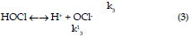
The generated hypochlorite ions act as main oxidizing agent in the pollutant degradation. The direct electro-oxidation rate of organic pollutants depends on the catalytic activity of the anode, on the diffusion rate of the organic compounds in the active points of anode and applied current density. A generalized scheme of the electrochemical conversion/ combustion of organics of pollutant (Panizza et al., 2004) on noble oxide coated catalytic anode (MOx) is given below. In the first step, H2O is discharged at the anode to produce adsorbed hydroxyl radicals according to the reaction.

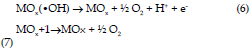
In the second step, generally the adsorbed hydroxyl radicals may interact with the oxygen already present in the oxide anode with possible transition of oxygen from the adsorbed hydroxyl radical to the oxide forming the higher oxide MOx+1.
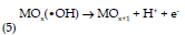
At the anode surface, the “active oxygen” can be present in two states. Either as physisorbed (adsorbed hydroxyl radicals (•OH) or/and as chemisorbed (oxygen in the lattice, MOx+1). In the absence of any oxidizable organics, the “active oxygen” produces dioxygen according to the following reactions:
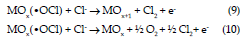
When NaCl is used as supporting electrolyte Cl ion may react with MOx(•OH) to form adsorbed OCl radicals according to the following (Raghu et al., 2007):

Further, in presence of Cl ion, the adsorbed hypochorite radicals may interact with the oxygen already present in the oxide anode with possible transition of oxygen from the adsorbed hypochorite radical to the oxide forming the higher oxide MOx+1 according to the following reaction and also MOx(•OCl) simultaneously react with chloride ion to generate active oxygen (dioxygen) and chlorine according to the following reactions:
In the presence of oxidizable organics the physisorbed “active oxygen” (•OH) should cause predominantly the complete combustion of organics and chemisorbed will participate in the formation of selective oxidation products (Vlyssides et al., 2004) according to the following reactions:
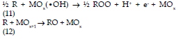
The physisorbed route of oxidation is the preferable way for polluted water treatment. It is probable that dioxygen participates also in the combustion of organics according to the reactions, such as formation of organic radicals by a hydrogen abstraction mechanism: RH+ •OH→R+H2O; reaction of organic radical with dioxygen formed at the anode: R• +O2 → ROO• and further abstraction of a hydrogen atom with formation of an organic hydrogen peroxide (ROOH) and another radical; ROO• +R’H → ROOH+R’. Since the organic hydrogen peroxides formed are relatively unstable, decomposition of such intermediates leads to molecular breakdown and formation of subsequent intermediates with lower carbon numbers. These sequential reactions continue until the formation of carbon dioxide and water. In this case the diffusion rate of organics on the anode area controls the combustion rate (Panizza et al., 2001 and Vlyssides et al., 2004). In the same way indirect electrochemical oxidation mechanism has been proposed for metal oxide with chloride as supporting electrolyte for wastewater treatment (Buso et al., 2000 and Rajkumar et al., 2003). The role of hypochlorite in electrochemical treatment of dye effluent via chlorine generation is
\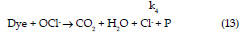
Since dye molecules of the effluent are electrochemically inactive, the reaction occurs at the anodes is chloride ion oxidation with the liberation of Cl2, which is a robust oxidizing agent. As regards to the reactions in the bulk, gaseous Cl2 dissolves in the aqueous solutions due to ionization as indicated in Eq. (2). The rate reaction is less in acidic solution due to OH- instability and considerably more in basic solution due to ready formation of OCl- (pKa 7.44) ion in Eq. (3) implying that the basic or neutral PH conditions are more favorable for conducting reactions involving Cl2. A cycle of chloride–chlorine– hypochlorite–chloride takes place, which produces OCl-. The pseudo steady state theory can be applied to each of the intermediates products (HOCl and OCl-) taking part in the bulk solution. Taking all other reactions are irreversible processes, the rates of reactions ri specifically for the sequence are (Eqs. (1) – (3) and (13))
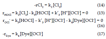
Then using Eqs. (15) and (16) we can easily deduce the following expression:

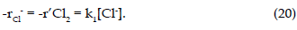
Finally, as regard to bulk solution, it is also to be noted that -rCl2 = rCl- from material balance of Eq. (13), that is

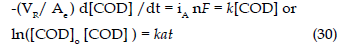
where the rate of reaction ri and the rate constants ki (i=2, 3 and 4) are defined with respect to bulk and the rate expression for main electrode reaction as per the Eq. (1) can be written as.
where k1 is heterogeneous electrochemical rate constant. Hence, in the following section an attempt has been made to establish a relation between the reacting species in bulk and at the electrode surfaces. The basic relationship applicable to all electrochemical reactions is Faraday’s law that relates to the amount of substance reacted at the surface to the charge (IAt) passed is MAIAt/nF (assuming 100% current efficiency) and the characteristic measurable parameter is current density, iA, which is IA/ Ae. Thus, the electrochemical reaction rate (for the disappearance of reactant A) can be expressed as

where IA is the current passed in time t, MA the molecular weight, n the number of electrons transferred per mole of reaction, Ae the electrode area, VR the reactor volume and F is the Faraday (96,500C or As/mol). It has to be noted -rA = -d[A]/dt = iA a/nF, where a is specific electrode area (Ae/VR). Assuming the main electrode reaction is governed by a simple Tafel type expression, then
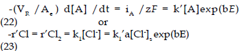
The reaction may be assumed to be under diffusion control as the reacting species, Cl- in the electrolyte is dilute. The reactant Cl- is transported for the bulk to electrode surface where it under goes electrochemical oxidation to Cl2 and it may be transported back to bulk by diffusion reaction in the bulk. Then,
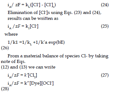
During electrolysis, since the constant current is applied, the rate of generation of [OCl-] will remain constant under a given set of experimental condition, but it varies as the applied current is altered. Then

Adopting the same classification for the reactors as for conventional reactors, thus the electrochemical reaction rate (for removal of COD) can be expressed as
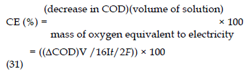
In electrochemical conversion the high molecular weight aromatic compounds and aliphatic chains are broken to intermediate products for further processing. In electrochemical combustion, the organics are completely oxidized to CO2 and H2O. The progress of the destruction of the organic pollutant has been monitored by COD estimation. The potentials required for oxidation of organic pollutants are generally high and the production of oxygen from the electrolysis of water molecules may determine the reaction yield. The current efficiency of the electrolysis can be calculated based on which is defined as follows:
The instantaneous current efficiency (ICE) may be computed from (instantaneous) difference between two values of COD of the solution as follows (18):

where CODt and CODt+Δt are the values of the chemical oxygen demand at times t and Δt, respectively, V the volume of the effluent in liters, I the current (A) and F is the Faraday constant. If the parameter ICE is plotted as function of time, the area under the curve integrated, the result divided by the total time (τ) elapsed up to the point when ICE = 0, an average current efficiency is obtained that is called the electrochemical oxidability index (EOI):

By calculating the fraction of current that oxidizes the organic species and converting it to its equivalent in grams of oxygen per gram of the organic species have been used to define the electrochemical oxygen demand (EOD). Since t is the time elapsed until electrolysis is essentially complete (i.e. ICE≈0), one can replace τ for t; hence, the electrochemical oxygen demand is defined as

Where ‘gorg.’ is gram of organic pollutant present. The ICE and EOD have been estimated for all the experimental runs in the present investigation and critically examined.
All the reagents used were of AR grade. NaCl was used as supporting electrolyte (PRIYA FINE CHEMICALS) and synthetic 3,3’-Dimethoxy Benzidine (3,3’-DMB) effluent have been used for the electro-oxidation in the present study. The color index of the dye was 37,235. It contains two chromogenic systems. The structure of dye is given in Fig. 1.

Fig. 1 The structure of 3,3’-Dimethoxy Benzidine (3,3’-DMB).

Fig. 2 The schematic diagram of experimental set-up. 1: power supply; 2: anode electrode; 3: cathode eletrode; 4: electrolytic cell; 5: stirrer bar; 6: magnetic stirrer.
Experimental set-up and procedure for electrolysis
The schematic diagram of the experimental set-up given in Fig. 2 The electrochemical cell consists of an undivided reactor with two cathodes and one anode.
It had a cell volume of 400 mL. These electrodes were parallel. The anode electrode is in the center of cell and was made of Graphite plate (20 mm × 20 mm ×1 mm); Stainless Steel 304 plates (20 mm × 80 mm ×1 mm) were used as cathodes. Experiments were carried out under galvanostatic condition conditions using a DC-regulated power source (HIL model 3161) of 0–2A and 0–30V. Stirring was done with a magnetic stirrer. Electrolysis was carried out under batch mode. The effluent volume of 75 mL containing dye initial concentration: 0.33 g L-1 (CODi: 350 mg L-1); supporting electrolyte concentration: 0.5 g L-1; pH 4.5 was taken for all experiments. Electrolysis was carried out at different current densities, viz. 1, 2, 3, 4 and 5 A/dm2. During electrolysis, samples were collected at different time intervals and the COD was measured.
Analytical measurements
The pollutants concentrations are presented in terms of chemical oxygen demand. The samples were subjected to COD analysis and the analysis was made by strictly following the APHA method 26. UV–Vis spectra of untreated dye effluent and treated effluent were measured by using a UV–Vis spectrophotometer (Systronics 118) and HPLC was carried out using Shimadzu model LC8A preparative liquid chromatograph along with Shimadzu SPD6A spectrometric detector. The 100% methanol and the mixture containing 70% methanol (HPLC grade) and 30% water were used as a solvent and effluent. ODS (octa decylsilane) column was used for separation.
For reuse study, the dye bath has been prepared in accordance with dye recipe, i.e. 0.33% of dye, 10% glauber salt, 1% acetic acid. Pre-weighed dye and fresh water soaked wool fabric was introduced into the cold dye bath. The dye bath temperature gradually elevated to boiling in 20 min time and maintained for about 1hour. The water level in the dye bath has been maintained during the dye processing. The dyed fabric was rinsed with cold water and dried under the shade, then subjected for dye uptake studies. The effluent generated during dyeing process has been collected and treated electrochemically and the treated polluted water then subjected for dyeing application. The procedure has been repeated for several times in order to check the reusability of electrochemically treated polluted water for dyeing application.
Electro-catalytic treatment
The results of the experiments on electro-catalytic treatment of textile effluent carried out covering wide range in operating conditions are presented in Figs. 3–9 and in Tables 1 and 2. The rate of COD reduction has been plotted as COD/CODi versus electrolysis time.

Table 1. Characteristics of effluents and treated effluents of 3,3’-Dimethoxy Benzidine (dyeing performed with glauber salt)

Table 2. Dye uptake values of woolen fabric with 3,3’-Dimethoxy Benzidine (dyeing performed with glauber salt)

Fig. 3 Influence of the current density on COD/CODi
with electrolysis time.

Fig. 4 The effect of pH on pollutant degradation; dye initial concentration 0.33 g L-1; supporting electrolyte concentration 0.58 g L-1; current density 3 A/dm2
Fig. 4 The effect of pH on pollutant degradation; dye initial concentration 0.33 g L-1; supporting electrolyte concentration 0.58 g L-1; current density 3 A/dm2

Fig. 5 The effect of supporting electrolyte concentration on pollutant degradation. Initial dye concentration 0.33 g L-1; current density 3 A/dm2.

Fig. 6 The effect anode material on rate of degradation; supporting electrolyte concentration 0.58 g L-1; current density 3 A/dm2; pH 4.5.

Fig. 7 Variation of ICE along with COD reduction with current density; supporting electrolyte concentration 0.58 g L-1; current density 3 A/dm2; pH 7.

Fig. 8 Variation of transfer coefficient with current density; supporting electrolyte concentration 0.58 g L-1; pH 7.

Fig. 9 UV–vis spectra and HPLC chromatogram of raw and electrochemically treated 3,3’- Dimethoxy Benzidine dye polluted water.
It can be ascertained from Fig. 3 that the rate of COD reduction decreases with electrolysis time. The rate of degradation is high at the beginning of the process and reduces gradually to a monotonical value at the end noticed from the figure that the rate of degradation increases with applied current density. This can be explained that the rate of generation of hypochlorite ion increased with current density, which eventually increases the pollutant degradation. Notice that the rate of degradation increased significantly when the current density increased from 1 to 5 A/dm2 and becomes insignificant beyond 3 A/dm2.
The influence of electrolyte pH on pollutant degradation has been verified with experiments conducted under acid, alkaline and neutral conditions. The observed results are presented in Fig. 4. The rate reaction is less in acidic solution due to OH- instability and considerably more in basic solution due to ready formation of OCl- ion in Eq. (3) implying that the basic or neutral PH conditions are more favorable for conducting reactions involving Cl2.
The influence of supporting electrolyte (NaCl) concentration on the pollutant degradation rate has been tested for three different concentrations with an initial dye concentration of 0.33 g L-1 and the current density of 3 A/dm2 (Fig. 5). It can be noticed that the rate of degradation increased with supporting electrolyte concentration. At lower chloride concentration, the pollutant degradation is small compared to higher chloride concentration. This is due to the fact that the oxide coated electrodes have low overpotential for oxygen evolution and then this secondary reaction is favored in comparison with organic oxidation. On the other hand, notice that beyond the electrolyte concentrations higher than 0.58 g L-1, no significant influence on the rate of degradation.
Four different anode materials graphite, Pt, Stainless Steel (304) and Pb/PbO2 have been used in the present investigation and the influence of anode material on rate of oxidation is given in Fig. 6. While Graphite is used as electrode the overpotential is very less when compared with PbO2 electrode. The results implies that the 3,3’-DMB degradation on the surface of Graphite occurs highly when compared with PbO2. The reason may be attributed to the high number of active sites on Graphite surface and more convenient adsorption of O2 and chloride species which would lead to the higher formation rate of OCl– on the surface of electrode. The process would also enhance the degradation rate of 3,3’-DMB. Say for example, at given electrolysis time of 50 min, graphite anode shows more than 25% COD reduction than lead oxide anode.
As stated earlier, the instantaneous current efficiency (ICE) was calculated for all the experiments in the present investigation. The variation of ICE along with percentage of COD reduction with current density is given in Fig. 7. It can be ascertained from the figure that the percentage COD reduction and instantaneous current efficiency (ICE) increased with increase in current density initially and decreases beyond certain current density value. However, the ICE and percentage COD reduction show decreasing trend beyond the current density of 3 A/dm2. The rate constant, k was estimated from the plot of ln COD/ CODi versus electrolysis time. The rate constant has been estimated for all the experimental runs carried out in the present investigation. Fig. 8 shows the variation of reaction rate constant with current density. At low current density, reaction may be dictated by Eq. (28) rather than Eq. (30). The increase in reaction rate constant becomes insignificant beyond the current density of 3 A/dm2.
Spectral and chromatograms analysis
Typical UV spectra and of untreated and treated effluent have been done for the effluent used in the present investigation. The retention time for the peak of 3,3’-Dimethoxy Benzidine is 3.05 min. The typical spectral and chromatogram analytical results of raw and treated effluent are given in Fig. 9.With regards to UV spectra, it can be ascertained from Fig. 9 that the raw effluent has the band a wide and medium absorption band with the maximum at 560 nm and a wide absorption band of very high intensity below360 nm. It has been observed that the absorption around 560 nm disappeared quickly and the degree of peak below 360 nm has been reduced smaller value. The reduction of peak around 560 nm indicates the destruction of higher organic carbon. The HPLC chromatograms raw and treated dye effluent is given in the same Fig. 9. It has been noticed from the figure that the raw dye effluent has several peaks with maximum peak at 3.05 min and these peaks are reduced in the treated effluent.
Reuse study
As stated earlier, it attempts in the present investigation to reuse the electrochemically treated wastewater for fabric dyeing application. The characteristics of ground water, effluents and treated water (treated effluent) are tabulated in Table 1 along with the experimental conditions. Table 1 is presented as follows. The characteristics of effluent and treated effluents are presented in row A and B, respectively, and the first column represents the parameters. The column labeled I of row B represents the quality of ground water. The ground water was used for dyeing process and the characteristics of effluent generated during dyeing process performed with ground water is presented in the column I of row A in Table 1. The untreated effluents characteristics is column I of row A in Table 1 was treated electrochemically as explained earlier and characteristics of the treated effluent is given in column II of row A in Table 1. Accordingly, the entire Table has been prepared. It can be noticed from Table 1 that the ground water quality (column I of row B) is within the acceptable limit for dyeing process. Notice that the treated water of first cycle dyeing process (i.e. column labeled II of row A) has high COD, chlorides content and total solids compared to the groundwater. This is due to the presence of glauber salt, broken dye fragments and the treated have been subjected for dyeing process (second cycle) and the quality of effluent generated is given in the column II of row A. This exercise has been repeated for several cycles and each cycle the effluent and treated water quality have been analyzed. Similarly for example, column V of row A represents the characteristic of untreated effluent generated during dyeing process performed with treated effluent, whose the characteristics of is given in column labeled IV of row B. Notice that TDS, TSS and TS do not affect the dyeing process these parameters are ignored in the present study. The residual chlorine content varied from 22.15 to 128.47 ppm.
The dye uptake of fabric has been measured using spectrophotometer (Hitachi, 3200) and the results presented in Table 2. It can be ascertained from Table 2 that the K/S value for ground water dyeing process is 0.114 and it varied from 0.087 to 0.1 for the dyeing process performed with electrochemically treated textile effluent. It has been observed from the present investigation that the K/S values of reuse studies lies within the limit and has the quality of dyeing.
Experiments were carried out in a batch electrochemical cell for simultaneous color removal and COD reduction in the dye effluent. The following conclusions can be made:
1. The COD reduction is significantly affected by the initial pollutant concentration, supporting electrolyte concentration and pH.
2. The treated water can be reused for effective dyeing process.
3. It has been observed from the present investigation that the quality of dyeing process performed with electrochemically treated polluted water is in par with conventional dyeing process.
4. The water consumption in textile industries can be minimized significantly by adopting this technique.
5. This method effectively reduces the environmental pollution since the polluted water is recycled and the organic pollutants are oxidized electrochemically.
Copyright © 2026 Research and Reviews, All Rights Reserved