
ISSN (0970-2083)
ISSN (0970-2083)
Dmitriy Vladimirovich Moldovan and Vladimir Ivanovich Chernobai*
Saint-Petersburg Mining University, 2, 21 Line, Saint Petersburg, 199106, Russia
Received 29 May, 2017; Accepted 04 June, 2017
Visit for more related articles at Journal of Industrial Pollution Control
The paper is concerned with the problem of the blasting energy application efficiency improvement during the huge blasts at the construction materials open-casts located in the Leningrad Region. The particle size distribution tests and the geometrics determination of the rock pile were performed at the open-casts of CJSC "Kamennogorskoe kareroupravlenie". The assessment of the rock pile quality after blast was performed and the gravimetric composition quality of the broken rock mass was also performed. On the basis of the performed measurements of the rock mass gravimetric composition, it was found that the application of the new design charges allows for the two-fold reduction of the oversize pieces content and the rock fragmentation quality improvement (it means the increase in the medium-size pieces amount nearly by the quarter of the blasted rock mass total volume). The application of the new design charges also allowed for the pile dimensions optimization, which in its turn permitted to use the loading machinery to the maximum extent possible. Jr. of Industrial Pollution Control 33(1)(2017) pp 1007-1012 www.icontrolpollution.com Review *
Blast, Stemming, Gravimetric composition, Rock pile
The bore-hole blasting of the rock mass is the most widely-used method at the modern open-casts. In this, the bore-holes can be horizontal, vertical or inclined. Practical and theoretical investigations have shown that the fragmentation quality, as well as the technical and economic indexes, depends on the adequate choice of the drilling and blasting operations parameters. The selection of the optimal process variables values ratio during the drilling and blasting operations designing still remains the crucial scientific and engineering problem.
During the open-cast field development, the bench roof of the underlying formations is sufficiently damaged by the charges blast in the bore-holes subdrills of the overlying formations. The broken bed with the depth of up to four meters has an impact on the intensity of the stress waves being incident and reflected from the free surface of the blasted bench roof in the direction of their intensity decrease. In practice, the intensity decrease can be compensated either by the charge mass increase in the bore-hole, which will result in the powder factor increase and consequently in the blasting operations cost increase, or by the subdrill value reduction, which will permit to lift up the charge column and to enhance the influence of the stress waves on the bore-hole collar. The subdrill value reduction can be performed by the increase of the bottom resistance line (BRL) by means of the near-vertical bench slope formation, or it is required to increase the time of the detonation products (DP) exposure on the rock.
The maximum DP energy transmission to the fractured rock can be achieved by means of the DP blocking in the bore-hole for the required time period. The interception of the gaseous explosion products outflow can be implemented by the usage of the different stemming types. The traditional stemming by the sand or the drill cuttings is the most common stemming type. However, the time of the detonation products interception (7 ms to 8 ms) is not always sufficient for the maximum DP energy transmission to the fractured rock. The special design stemming can be used for the longer-term blocking of the explosion products in the bore-hole.
It is known that the stemming has a significant impact on the blast efficiency improvement during the rocks fragmentation.
The following leading scientists dealt with the rock fragmentation quality improvement problem solving by the usage of different stemming types: (Seinov, et al., 1972; Paramonov, et.al., 1998; Menzhulin, 1995) the following scientists were engaged in the process modeling: (Aleksandrova, 2000; Sher, 1982; Sher and Aleksandrova, 2000; Repin, 1965; Repin, 1963; Repin, 1973; Fokin, 2004; Makarev, 1972; Makarev, 1981; Makarev, 1975; Makarev and Mikhailov, 1984; Makarev and Korotkov, 1970; Potresov, et al., 2003; Zhurkov, 1980; Zhurkov, et al., 1981; Zhurkov, 1957; Zhurkov, 1977).
The stemming quality depends heavily on the applied material. The ease of handling and the low cost are the basic requirements applied to the stemming material.
As for today according to the stress-strain properties and the ability to resist the gaseous DP, the following stemming types are used: the stemming performed of the plastic materials (such as clay and sand-clay); the fine-grained stemming (sandy, slaggy, made of the drill cuttings); the coarse-graded stemming (made of the break stone or the break stone and sand mixture).
Mindeli, et al., 1970 were the first to study the complex behavior of motion of the different compressible granular stemming beds during the blast-hole charges shot (Mindeli, et al., 1970).
It was found that the time dependence of the longwall incompressible stemming (bar) motion speed is of the form of the parabolic curve and does not follow the granular stemming material motion law. Consequently, the electromagnetic method of the displacements measurement (Drukovanyi, et al., 1980) was used for determination of the motion speed of the stemming made of the different materials with consideration of the stemming beds compressibility.
For other materials, the stemming motion speeds are similar and differ only by the inclination angle and the motion duration. The motion speed behavior is different for different stemming beds.
In case of the exposure of the shock wave and the explosion products pressure on the stemming end, the stemming motion speed is increased. It results in the stemming material consolidation and the occurrence of the friction resistances due to the horizontal stress. The stemming is in the combined stress state due to the gases pressure and the borehole walls response. The system is at equilibrium for a definite time period until the stemming material is sheared or the rock surrounding the stemming is destroyed.
When the shock pulse is received by the stemming bottom, the pulse energy is transferred to the adjacent parts, which results in the sudden compression of the stemming material and the friction forces increase between the stemming material particles as well as between the stemming and the bore-hole walls.
Due to the stemming bottom overconsolidation, the stemming motion speed is decreased. The shear stresses become equal to the viscosity stresses. The stemming is at equilibrium, but in case of the shear stress increase, the stemming is sheared and due to the viscosity stresses increase the stemming does not slip but it is cut off over the cylindrical surface which is closely approximated to the bore-hole side surface, and the stemming flies out at a growing rate. When the stemming is cut off its weight and the friction force obstruct its movement, which should be considered during the stemming head motion speed determination (Drukovanyi, et al., 1980). Due to consolidation, the stemming head motion starts at a later time at a growing rate and it is finished after the stemming fly out from the bore-hole collar. Hence, it can be assumed that there exists the critical stemming length, for the space of which the material is compacted, while the remaining part is the inertial barrier to the lower beds fly out.
Special attention is given to the determination of the well-proportioned stemming during the blasting operations parameters calculation. Different methods of the well-proportioned stemming determination are suggested. The present methods are based on the assumption that the stemming fly out time should be more than the time required for the rock mass destruction or more than the time of the high detonation of the charge. Assuming that the rock mass destruction is induced by the combined action of the gaseous explosion products pressure and the stress waves energy, it should be considered that the optimal stemming length is the length which impedes the gaseous explosion products for the period of time required for the rock destruction.
It follows from the papers analysis, that the stemming length is increased with the growth of the charge length, the medium bore-hole pressure, the bottom resistance (BR) value and the bore-hole diameter, while the stemming length is decreased with the growth of the stemming material pieces size (up to the definite limit value), the stemming material density, the strength and the internal friction coefficient.
The sand with the gypsum plug offers the greatest resistance to the blast effect, and the following materials offer resistance in descending order: milled dry shale, lime and sand mixture, lime dust, green sand, a mixture of clay with humidity of 7% and sand, a mixture of clay with humidity of 14% and sand and green clay. The high efficiency of the friable materials is caused by their low internal fracture value.
The new type of the developed graded stemming, that is, the blocking gas-dynamic device (BGDD), permits to impede the explosion products emission from the charging cavity for 15 ms to 25 ms, in other words, practically until the beginning of the rock fragmentation process.
The stemming has the shape of cylinder, the external diameter of which is commensurable with the borehole diameter and the axial internal cavity in the form of the prolate semisphere and the frustum of cone. The stemming bottom is placed on the drill cuttings fine bed, which guards it against the burnoff and ensures the additional propping in case of the gap between the stemming and the bore-hole walls (Fig. 1).

Fig. 1 The bore-hole charge design: 1 is the stemming made of drill cuttings; 2 is the BGDD; 3 is the band made of the drill cuttings; 4 is the explosive.
The drill cuttings bed borders closely to the explosive charge. The structurally tested stemming is made of the hollow thin-walled cylinder with the cone of the same thickness made of the plastic polymer material, in this case the space between the cone and the cylinder is filled by the inert material, ensuring the product weight margin.
In this case the following is achieved:
• the assurance of the stemming operation time, required for the maximum use of the gaseous explosion products energy;
• the simplification of the stemming arrangement inside the bore-hole in case of different drilling-out coefficients and the bore-hole walls roughness due to the construction stretchability improvement;
• the significant cost reduction of the product due to the material saving.
The thin band of the fine sand should be provided between the stemming and the explosive charge for the stemming protection against the burn-off. The present band ensures the additional propping in case of the gap between the stemming and the bore-hole walls. Hence, the use of blocking devices provides the reliable blocking of the charging cavity for a time required for the maximum use of the gaseous explosion products energy and permits to reduce the special consumption or the scope of drilling.
The supersonic diffuser shape is selected for the internal compression waves or the shock waves system with the purpose of the DP flow deceleration improvement. When the gas passes through the compression wave, it is compressed and the flow is deflected at an angle δ upstream the undisturbed flow direction (Mironov, 1998). In case of the gas increase in the wave, the deviation angle is also increased and the present wave is called the shock wave.
When the flow passes through the present wave, the flow parameters, such as the pressure and the speed are being changed in discrete steps. The shock position is determined by the angle β between the shock plane and the initial direction of the flow.
The inlet wall inclination angle is not more than 3° to 5º, which results in the shock cone formation. Due to the smooth concavity of the walls profile, the flow is rotated in each point at a small angle δ, passing through the inlet section, the DP waves speed becomes supersonic. At the diffuser outlet, the DP waves speed is decreased up to the subsonic values.
The inlet diameter is equal to the explosion chamber diameter. Then the total flow rotation angle is determined. And the shocks number is selected according to the flow speed. The supersonic diffuser profile is determined by the following inlet parameters (Baron, et al., 1961):
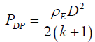 (1)
(1)
where PDP is the detonation products pressure, ρE is the explosive density, D is the detonation speed, k is the isentropic coefficient (at the initial blasting period k = 3).
The detonation products density is as follows:
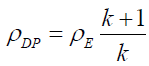 (2)
(2)
The DP flow outlet speed is as follows:
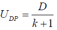 (3)
(3)
According to (Efremov, et al., 1984) the DP consumption and the critical outlet speed are determined from the following relations:
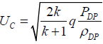 (4)
(4)
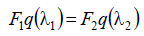 (5)
(5)
Where F1, F2 are the inlet and the outlet cross section areas, respectively,
q(λ1), q(λ2) are the gas-dynamic detonation products functions at the inlet and the outlet, respectively.
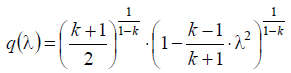 (6)
(6)
Where  is the inlet specific DP speed.
If q(λ2)=1 the outlet gas speed is equal to the sound speed. The outlet section radius is as follows:
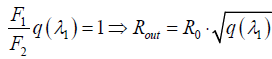 (7)
(7)
For the diffuser convergent section length calculation, the relative speed M=c/a (the Mach number) is introduced; c is the flow speed (UDP), a is the local sound speed.
The verification by the dimensionless outlet speeds ratio is performed with the use of the following relation (Deich, 1974):
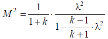 (8)
(8)
According to the M number at the outlet and the applied stemming material, the shock sections number is selected: n inclined shock waves and one normal barrel shock, located upstream the inlet.
The stemming operation concept is as follows: the detonation wave refraction to the bore-hole space is followed by the shock wave interaction with the stemming inlet and the thrust of the internal surface of the cone walls prolate semisphere. In this case, the inert material between the cone and the cylinder walls serves as the shock absorber and it is involved in the further formation of the melted material.
The measurements were carried out at the CJSC "Kamennogorskoe kareroupravlenie" of the "Ostrovskoe" open-cast. The bench located at the second horizon was selected for the experiment conduction. Then the two adjacent blocks located at the bench mentioned above were selected. The first block was charged by the standard method, used at the present plant, the second one was charged with the use of the BGDD, the gas-dynamic stemming, developed by the Saint Petersburg Mining Institute. The general data on the blocks are presented in Table 1.
| 14 blocks | 15 blocks | |
|---|---|---|
| Design volume, m3 | 7000 | 7300 |
| Bore-holes number, pcs | 90 | 97 |
| Bore-holes diameter, mm | 115 | 115 |
| Bore-hole pattern a × b, m | 3 × 3 | 3 × 3 |
| By the first-row a, m | 2.5 | 2.5 |
| Subdrill value, m | 1.5 | 1.5 |
| Bore-holes depth, m | 9.0-9.5 | 9.0-10.5 |
| Horizon, m | +18 | +18 |
| Stemming | standard | BGDD |
Table 1. Drilling and blasting parameters for the blocks 14 And 15
The blasting operations were performed by the standard explosives, available at the plant, that is, the granulotol and grammonite 79/21 with the specific consumption of 0.97 kg/m3. The diagonal-wedge initiation scheme was used in both cases.
The gravimetric composition of the rock mass was evaluated after the blast. The measurements were performed by the following three methods: the photo-planimetric analysis, the qualitative analysis and the screen analysis.
The processed gathered data are presented below in Fig. 2.

Fig. 2 The grade yield data on 14 and 15 blocks, obtained by the photo-planimetric method.
The oversized grade, which remained after the excavation, was measured at the four blasted blocks: at the blocks 14 and 15, which were drilled by the diameter of 115 mm, and at the blocks 4 ("Ostrovskoe" open-cast) and 14 (“"Kamennogorskoe" open-cast), which were drilled by the diameter of 165 mm..
Then let us calculate the rockpile parameters after blast on the basis of the technique (Kazakov and Viktorov, 2003).
The comparison of the theoretical data and the data obtained at the open-cast is presented in Table 2.
| Theoretical calculation of the rock pile parameters | The rock pile parameters with consideration of the BGDD | |
|---|---|---|
| Height, m | 6.5 | 6 |
| Width, m | 23.5 | 30 |
Table 2. Comparison data of the pile parameters
The analysis of the gravimetric composition measurements results shows that there is practically double reduction of the oversized grade yield (screened out grades) in case of the BGDD application as compared to the standard stemming.
The oversized grade: at the 15 block is 1.75%, at the 14 block is 3.76% (for the diameter of 115 mm), at the 4 block is 2.9%, and at the 14 block is 3.76% (for the diameter of 165 mm).
The theoretical and experimental data show that the pile height was reduced by 8%, and the pile width was increased by 27.5%.
The results of the industrial tests of the multicharges with the BGDD have shown the enhancement of the blasting energy application efficiency, which allowed for an approximately double reduction of the oversized grade yield and the rock fragmentation quality improvement (it means the increase in the medium-size pieces amount) by 15% to 20% and also the formed rock pile improvement for the mining loading machinery operation.
Copyright © 2026 Research and Reviews, All Rights Reserved